To all the tubelab fans,
Tonight my SimpleSE blew its right channel, again. Just a little info about the amp. It was built in the spring of 2008. Its pretty much stock job with edcor power and output transformers, a hammond choke, and a 30uf motor run cap. I have ss rectifiers installed, but rarely use them, they were not turned on when the amp blew. B+ with 5ar4 is around 400. Power tubes are 6l6's.
About nine months after building (and loving) this amp, R17 blew. I was five feet away from the amp and noticed static coming from the right channel followed by smoke from around one of the tubes. I quickly turned it off, let it cool down, and turned it over (it has a plexiglass bottom) and saw that R17 was now dark brown. I'm not certain what the original value of it was, but I believe it was 390R. I replaced it at that point with a 450R. I also suspected at this time that c12 was slightly bulged, but being ignorant I fired it up and it came back to life.
6 months later, c12 blows. I changed it out along with c22 thinking maybe they were from a bad batch. They were both originally the panasonics that George had spec'd out. I replaced them with 63v nichicons thinking this may help to prevent any future problems.
Well tonight I was in another room when I smelled that terrible smell again. C12 is again blown.
I'm not quite sure where to go from here, but I know a few of you may have some ideas.
Thanks,
Phil
C12 or C22 will "go" if you put too much voltage across them. Under normal circumstances, a 63V rating should be more than plenty. The voltage across that cap will depend on how much current your power tube draws, and the value of the cathode resistor R17 or R27. If you have a 450 ohm resistor, your tube would have to draw over 140 mA to exceed 63 volts across the cap. That's a lot of current, and you should see other signs of problems well before the cap goes.
R17 or R27 will cook and turn brown if you draw too much current through them. They should be cemented power resistor types, rated for at least 5 watts. To exceed 5 watts on a 450 ohm part you would have to draw over 105 mA. Again, any 6L6 type would show signs of distress under that kind of continuous current.
Regardless, you've toasted both the resistor and the cap. Something funny is going on.
I'd like to know the cathode voltage (voltage across R17) while the amp was working. I think that might tell us something.
I figure if the tube were drawing 105mA idle current, that would put 47 volts across the 450 ohm resistor. You'd have five watts in the resistor (right at its rated limit) and 37 watts in the tube. Only problem is the 6L6GC shouldn't be passing that much current with 47 volts between G1 and K, and only 400 volts at the anode. Even if it were, 37 watts is too much for a 6L6GC. You should see signs of red plate or something.
I figure if the tube were drawing 105mA idle current, that would put 47 volts across the 450 ohm resistor. You'd have five watts in the resistor (right at its rated limit) and 37 watts in the tube. Only problem is the 6L6GC shouldn't be passing that much current with 47 volts between G1 and K, and only 400 volts at the anode. Even if it were, 37 watts is too much for a 6L6GC. You should see signs of red plate or something.
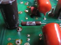
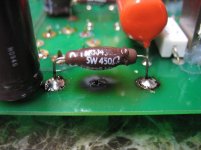
It sounds to me like R17 and 27 are under rated. What is the power rating of these?......it started off as a dark brown 5w dale cemented resistor.
It is pretty safe to assume that I have more experience abusing and blowing up Simple SE's than anyone. The only time I have seen the capacitors blow is when the resistor fails to an open circuit. A 5 watt resistor should be fins here since in normal operation it sees about 2 watts. I have always used the cheap Xicon resistors and I have only blown a few, and it took far more than 5 watts to do it. As stated it shouldn't be possible with a 6L6GC unless the tube was severely overloaded. I did it with some really gassy 6V6's and trying to run 6DQ6's in this board. Neither amp played undistorted music as it blew up.
Dale resistors are highly regarded and I use them with good results in Tubelab SE's. I can't see a 5 watt Dale failing where Xicons live. Are they really 5 watt units? Are they the same size as the Xicon's? The Xicons are 3/8 X 3/8 X 7/8 inch long. The current trend is to make resistors out of higher temp materials so that they can be smaller for a given size. This means that they will run hotter than a larger resistor at a given power dissipation. The problem?
Even with a large resistor the solder connections will go through repeated hot - cold thermal cycles. A smaller resistor makes this worse. It is also a good idea to space the resistor 1/4 to 1/2 inch above the board to help with the heat. It is possible that one of the solder connections experienced a momentary open circuit failing the capacitor and causing the crackle.
It is also possible that a tube experienced a momentary short, blowing the resistor and cap. Usually this results in visible fireworks inside the tube, but I have seen a tube develop a grid cathode short without fireworks, but it will grossly overheat (bright red glow) and cause a loud hum in the speaker.
If it was my amp I would replace both resistors and both caps. I would use a large (same size as the Xicon) resistor. 450 ohms may be to low since I use 470 ohms to 750 ohms depending on the B+ voltage and tubes.
Here we go now:
Sorry for the delay, I've been very busy wrapping up my final term at school and interviewing for jobs. First off, the resistors were ohmites and not dales as first posted, although I doubt that that makes much of a difference. As you can see from the attached pictures, they were mounted about a 1/2" above the board to help in dissipating heat. I should also mention that the ventilation should have been more than adequate, with over sized tube holes and 3/16" of clearance between the bottom plate and the chassis.
Now the fun part: what I failed to mention before is that every time this happened, it was with the same set of tubes, a matched pair of modern (Russian) Tung-Sol KT66 reissues. After the first time the resistor blew, I replaced the resistors and tried the tubes again. They worked as before, but then ~6 months later the caps blew. I then replaced the caps and bought a new pair of Sovtek 6L6 wxt+'s and installed them. Just before this last incident, I tested out the old KT66's on a B&K model 667 ss tube tester. The tubes tested well and no shorts were present, so I put them back in as I preferred their sound. I now thinking that this was the culprit. I will say that when I got to the amp this time, there was no glow in the tubes other than the heaters, however, the second time it blew, the tube plate was glowing a bright cherry red. An instructor at school who I borrowed the tube tester from said it was probably a grid to cathode short that may appear randomly. This concurs with George's assessment.
Anyways, I've ordered two new Panasonic 63v caps, and a set of both 450r and 470r 5W resistors, the 470's are per Georges recomendation. Hopefully I will get them tomorrow (one of the nice things about living in the same state as digikey is that if I put an order in before 8pm, I'll get them the next day ) so that I can install them at school with their wonderful Metcal soldering iron.
Another thing I noticed on the blown resistor is that the solder joint has changed from when I installed it, it now looks like a cold joint. This just goes to show that George knows his stuff. What came first (the bad joint or the wacky tube) may never be known, but maybe you fellas have some thoughts. I would also like to thank all of you for your input, and welcome any further suggestions.
-Phil
P.S. - I should also note that the resistors measured .2005" Diameter by .866" Length. Also after uploading the photos, I decided to take one of the opposite side of the board. Does anyone think that there may be damage to the board itself?
Sorry for the delay, I've been very busy wrapping up my final term at school and interviewing for jobs. First off, the resistors were ohmites and not dales as first posted, although I doubt that that makes much of a difference. As you can see from the attached pictures, they were mounted about a 1/2" above the board to help in dissipating heat. I should also mention that the ventilation should have been more than adequate, with over sized tube holes and 3/16" of clearance between the bottom plate and the chassis.
Now the fun part: what I failed to mention before is that every time this happened, it was with the same set of tubes, a matched pair of modern (Russian) Tung-Sol KT66 reissues. After the first time the resistor blew, I replaced the resistors and tried the tubes again. They worked as before, but then ~6 months later the caps blew. I then replaced the caps and bought a new pair of Sovtek 6L6 wxt+'s and installed them. Just before this last incident, I tested out the old KT66's on a B&K model 667 ss tube tester. The tubes tested well and no shorts were present, so I put them back in as I preferred their sound. I now thinking that this was the culprit. I will say that when I got to the amp this time, there was no glow in the tubes other than the heaters, however, the second time it blew, the tube plate was glowing a bright cherry red. An instructor at school who I borrowed the tube tester from said it was probably a grid to cathode short that may appear randomly. This concurs with George's assessment.
Anyways, I've ordered two new Panasonic 63v caps, and a set of both 450r and 470r 5W resistors, the 470's are per Georges recomendation. Hopefully I will get them tomorrow (one of the nice things about living in the same state as digikey is that if I put an order in before 8pm, I'll get them the next day
) so that I can install them at school with their wonderful Metcal soldering iron.Another thing I noticed on the blown resistor is that the solder joint has changed from when I installed it, it now looks like a cold joint. This just goes to show that George knows his stuff. What came first (the bad joint or the wacky tube) may never be known, but maybe you fellas have some thoughts. I would also like to thank all of you for your input, and welcome any further suggestions.
-Phil
P.S. - I should also note that the resistors measured .2005" Diameter by .866" Length. Also after uploading the photos, I decided to take one of the opposite side of the board. Does anyone think that there may be damage to the board itself?
Attachments
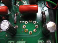
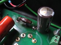
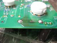
The board has been subjected to some serious heat. For those resistors to burn the board like that from 1/2 inch away they were eating far more than 5 watts probably like 50 watts. This almost has to be a bad tube, or an intermittent short in a coupling cap. Intermittent caps are rare and highly unlikely with a new cap like the orange drops. The burned spot in the board is not an issue in that particular location. A charred spot can become conductive if subjected to high voltage, but won't be an issue with 50 volts or so and no traces passing through the burnt spot.
If it were me, I wouldn't use the tube that glowed again since there is a good probability that it will happen again.
I use a Metcal at work. Best soldering iron on the planet, but far too expensive for me. I spend far too much time dealing with tiny SMD components under a microscope to put up with a crummy iron at work. The new no lead solder just makes matters worse.
Here, here, can I get a second on the motion?
The first time I used the metcal, all my previous education on soldering was lost. As long as you keep it clean, it almost solders by itself. Too bad, like everyone else, I can't afford one. Thank god for school. As for the tube, maybe I can finally have some fun with the 15kv neon transformer sitting on the shelf at school?
The first time I used the metcal, all my previous education on soldering was lost. As long as you keep it clean, it almost solders by itself. Too bad, like everyone else, I can't afford one. Thank god for school. As for the tube, maybe I can finally have some fun with the 15kv neon transformer sitting on the shelf at school?
- Status
- This old topic is closed. If you want to reopen this topic, contact a moderator using the "Report Post" button.
- Home
- More Vendors...
- Tubelab
- Blown SimpleSE