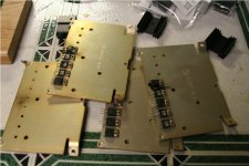
I'm struggling with the best solution for the semiconductor heatsinks. I'm thinking of mounting all of the semiconductors off-board. If I insulate all of them, can I run them off board to a common large heatsink? I was thinking of bolting several of these in the pic together...
Attachments
It may be workable but the wire length connecting back to TSE circuit board may cause issues with impedance. How far away will they be placed?
I'd keep it as short as possible. ie... just off of the board within an inch or two. I have some military grade 18g or 22g silver wire that I could use to keep the impedance effect low.
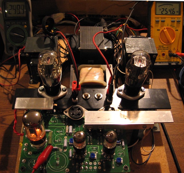
I envision a deep case with the board mounted just below the top plate. The heat sinks oriented vertically just off of the board within 1/2". Total wire length between the sink and the board from D1,U1 would be ~1-2" and Q1,2 U2,3 would be ~3-4".
Last edited:
The FETs are touchy about oscillation. Some ferrite beads may be needed on the leads of the gates. The dual rectifier and regulator pass large currents. 5A for 300Bs. Use a heavy gauge wire for these.
I opted for mechanical connection to a common heat sink. More work though and still only partially completed:
I opted for mechanical connection to a common heat sink. More work though and still only partially completed:
If I insulate all of them, can I run them off board to a common large heatsink?
Yes, there is no problem running all of the TO220 devices on the same heat sink. As Russ stated the CCS IC's and the Mosfets may oscillate if they are connected with wires. It may be possible to get by with short wires if stopper resistors are added to all of the gate leads right at the chip. A ferrite bead over the wire wouldn't hurt either. It is possible to use aluminum angle to heat sink the devices to the chassis or mounting plate with the devices still soldered into the board. Then use extensions on the sockets to raise them up to the chassis level.
It is possible to use aluminum angle to heat sink the devices to the chassis or mounting plate with the devices still soldered into the board. Then use extensions on the sockets to raise them up to the chassis level.
I see no really easy solution. This seems like it would work, but the extensions (wires) would have to be longer then truly needed in order to be able to solder everything together and bolt the angle to the top + heatsinks. (Unfortunately, I've already soldered the sockets to the board...so would have to unsolder them, or use the 2nd board that I purchased). Any limitation on the length of the extensions?
An easier alternate solution, but not as visually appealing would be to use the aluminum angle as indicated, but leave the sockets on the board. This would give the tubes a submerged look. Would that work?
It would. The 1.25" aluminum angle stock on mine is setup to be just under the top plate. The top plate will be positioned so that the noval "socket savers" for the 5842s are flush with it. I'm not using the on-board 4-pin sockets, but if I did the tubes would be recessed to the tops of the bases. The rectifier would be recessed a bit more. I like the recessed look and it also helps to force convection out of the top plate if you leave a wide enough gap.
It would. The 1.25" aluminum angle stock on mine is setup to be just under the top plate. The top plate will be positioned so that the noval "socket savers" for the 5842s are flush with it. I'm not using the on-board 4-pin sockets, but if I did the tubes would be recessed to the tops of the bases. The rectifier would be recessed a bit more. I like the recessed look and it also helps to force convection out of the top plate if you leave a wide enough gap.
That's exactly what I was looking at... 1.25" stock with a .1875" thickness. I was a little worried about how the recessed tubes would look but... my amp is going to look like Easter Island anyway...with all the film caps. Getting the layout right is the hardest part. Sooner or later you get tired of procrastinating and you make some less then steller choices and you live with them instead of remaking it with the improvements. It will be a while before I complete this as I can't afford the tubes and output xfrs at this time... but would like to get as far as I can without them. Can I test the PS portion without the 300B's and output xfrs?
Sooner or later you get tired of procrastinating and you make some less then steller choices and you live with them instead of remaking it with the improvements.
I heard that. The other alternative, as is the case with my preamp, is that you never finish it at all!
Yes, you can test the PS and also take the input/driver section for a test drive if you have a scope and so forth.
- Status
- This old topic is closed. If you want to reopen this topic, contact a moderator using the "Report Post" button.
- Home
- More Vendors...
- Tubelab
- TubelabSE heatsink question