Folks,
I'm playing with a circuit that's inspired by George's PowerDrive circuit. Like he, I'm using a source follower to drive a 300B. In my simulations, I have noticed that the grid current of the 300B gets rather high when the tube is driven hard into A2. Basically, with the source follower there is as much grid current available as the power supply can deliver.
But how much grid current can the 300B handle and would it make sense to limit the current to a safe&sane value by inserting a resistor in series with the drain of the source follower?
Thanks,
~Tom
Just to clarify (and maybe get a response): The PowerDrive circuit is what's used in the TubelabSE (5842 + source follower).
Am I the only one who's a little worried about driving a 300B to the point where it saturates the OPT? OPT saturation produces rude sounds in the speaker that aren't on the original program material. Nasty...
~Tom
Am I the only one who's a little worried about driving a 300B to the point where it saturates the OPT? OPT saturation produces rude sounds in the speaker that aren't on the original program material. Nasty...
~Tom
It seems like it is something one would have to try to see what happens. Wouldn't it depend on how much headroom the OPT in use has? So your question comes down to which is worse: clipping and blocking distortion due to insufficient grid drive or distortion due to oversaturation of the transformer?
The root of my question is this: When the source follower brings the output tube grid positive with respect to the cathode, grid current will flow in the output tube (300B in my case). The source follower is capable of supplying, basically, unlimited current (amps!). Is this safe/healthy for the output tube? If not, what would be a reasonable limit on the grid current?
Well... I "tried" in PSpice and noticed that the grid current of the 300B exceeded 70 mA. This made me wonder if this was safe (healthy for the tube) in the long run. Hence my original question.
It would depend on the air gap in the transformer, which is rarely specified. In my case, I'm using an Edcor CXSE25-8-5k. Edcor doesn't specify the max current or B field.
Blocking distortion sounds pretty bad, but I don't think it'll damage the tube or speakers. Clipping (running the output tube or driver stages into shut-off) doesn't sound good either, but isn't likely to damage the tube or speakers either. One could argue that if you leave the amp running in clipping for hours, the added power in the high-order harmonics would eventually make the tweeter fry, but I'll assume the user has turned down the volume by then due to crappy sound quality. All this I'm comfortable with. I am, however, NOT comfortable with the woofer of my speaker hitting the excursion limit when the output tube is driven so hard that it pulls 100's of mA through the OTP, thus, causing OPT saturation. Remember that when an inductor (or transformer) saturates, the inductor will basically act as if it had no core at all. So the inductance drops like a rock and the current shoots up. When the primary current shoots skywards so does the secondary current. This causes the woofer on my KRK R6 speaker to hit the excursion limit (I think it has shorting rings, otherwise it would have fried by now!) Not only does this make rude sounds not present on the CD, it also makes me worry for the overall safety and well-being of my speakers.
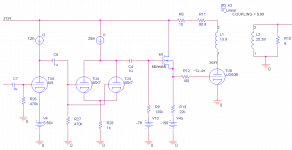
I should note that the circuit that is capable of driving the OPT into saturation has higher gain than George's original PowerDrive circuit. It's a 6J5 followed by a 6BX7 and is capable of driving at least a good 100~125 Vpeak before running out of gas. The 300B enters grid current once the drive voltage exceeds about 75 Vpeak...
Thanks,
~Tom
It seems like it is something one would have to try to see what happens.
Well... I "tried" in PSpice and noticed that the grid current of the 300B exceeded 70 mA. This made me wonder if this was safe (healthy for the tube) in the long run. Hence my original question.
Wouldn't it depend on how much headroom the OPT in use has?
It would depend on the air gap in the transformer, which is rarely specified. In my case, I'm using an Edcor CXSE25-8-5k. Edcor doesn't specify the max current or B field.
So your question comes down to which is worse: clipping and blocking distortion due to insufficient grid drive or distortion due to oversaturation of the transformer?
Blocking distortion sounds pretty bad, but I don't think it'll damage the tube or speakers. Clipping (running the output tube or driver stages into shut-off) doesn't sound good either, but isn't likely to damage the tube or speakers either. One could argue that if you leave the amp running in clipping for hours, the added power in the high-order harmonics would eventually make the tweeter fry, but I'll assume the user has turned down the volume by then due to crappy sound quality. All this I'm comfortable with. I am, however, NOT comfortable with the woofer of my speaker hitting the excursion limit when the output tube is driven so hard that it pulls 100's of mA through the OTP, thus, causing OPT saturation. Remember that when an inductor (or transformer) saturates, the inductor will basically act as if it had no core at all. So the inductance drops like a rock and the current shoots up. When the primary current shoots skywards so does the secondary current. This causes the woofer on my KRK R6 speaker to hit the excursion limit (I think it has shorting rings, otherwise it would have fried by now!) Not only does this make rude sounds not present on the CD, it also makes me worry for the overall safety and well-being of my speakers.
I should note that the circuit that is capable of driving the OPT into saturation has higher gain than George's original PowerDrive circuit. It's a 6J5 followed by a 6BX7 and is capable of driving at least a good 100~125 Vpeak before running out of gas. The 300B enters grid current once the drive voltage exceeds about 75 Vpeak...
Thanks,
~Tom
Last edited:
Am I the only one who's a little worried about driving a 300B to the point where it saturates the OPT?
If you are indeed hitting a 300B hard enough to saturate a CXSE25-8-5K then there may be cause for alarm. I have been known to push things as far as they will go, and I haven't seen this yet. The CXSE is a pretty big OPT and I haven't seen it saturate even when fed with glowing sweep tubes.
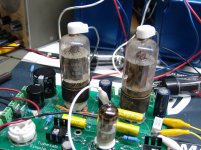
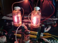
I enclosed two pictures of an extreme test of a pair of crusty old 6BQ6GA's that were found in a $5 box of tubes at a hamfest. These tubes were running at about 150 mA idle current and the amp was making 20 WPC at 3% distortion. No saturation was seen. I hooked this thing up to my speakers and it rocked.....for a short while. My CXSE's are the early versions that were painted "pimp my ride" metallic blue.
The PowerDrive circuit (as concieved) can indeed feed the grid of a tube as much current as it can eat. Under normal music conditions transitions into the positive grid current regions should occur only on transient peaks, unless you run your amp into clipping a lot. These conditions should not cause excessive G1 dissipation since the time in the grid current region is very low.
It should be noted that it might be possible to damage a tube by long term sine wave testing at or above the clipping level since the tube will see grid current on every cycle. I have not seen this happen on conventional G1 drive but I have melted a couple of screen grids using PowerDrive for screen drive. There are reports that excessive grid current might cause gold migration in tubes with gold plated grid wires.
You are reporting OPT saturation. This is a phenomenon where all of the OPT's magnetic headroom is used up. It is related to the DC current, the audio power level, the frequency of the audio signal, and the actual speaker impedance at that frequency. With my small speakers it is impossible to saturate a CXSE without blowing the output tube into 27 pieces, since the impedance of the speakers is in the 10 to 20 ohm range below 70 Hz. If your speakers have resopnse in the 40 Hz and below region, and the impedance is low enough, it might be possible to get some saturation in the low bass region. It will occur only on strong low bass notes, and does sound pretty nasty. On a scope OPT saturation will look like a divot taken out of the leading edge of the wave form just before the peak. If you are hearing nasty distortion when there are no strong bass signals present it is not saturation.
You mention a circuit using a 6J5 and a 6BX7 driving a 300B. Are you using the 6BX7 as a cathode follower to implement the PowerDrive circuit, or are you using two stages of gain before the mosfet follower?
Is the nasty sound you are hearing present on all frequencies, but only as the volume is turned up loud?
If the nasties are present without strong bass, and you are using a mosfet, I would bet there are short bursts of oscillation occurring just as the tube enters (or leaves) the grid current region. A scope may reveal this, but sometimes the oscillation will not occur with the scope probe attached to the circuit. Small valued (100 to 500 ohm) grid stoppers, ferrite beads on the grid and gate leads, and careful layout are your best defenses here.
Attachments
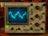
On a scope OPT saturation will look like a divot taken out of the leading edge of the wave form just before the peak.
Does it look anything like this? This is from a push/pull amp, but I'd imagine the manifestation should be similar. If I turn the volume down just a bit, the trace snaps back to a nice clean 20 Hz sine wave.
http://i69.photobucket.com/albums/i43/Ty_Bower/Oscilloscope/P1080401.jpg
Does it look anything like this?
YES. That is what saturation looks like in a P-P amp except for the little spike on the negative half cycle. In a SE amp the distortion is usually seen only on one half cycle since it is coincident with peak current through the OPT. Depending on your scope and the absolute polarity through the OPT it could be on the top or bottom.
If I turn the volume down just a bit, the trace snaps back to a nice clean 20 Hz sine wave.
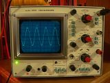
If you were to leave the volume in the same spot and increase the frequency the distortion should disappear. It would also be reduced if the load resistance was increased since the peak current through the OPT drops even though the voltage goes up.
If you were to leave the volume in the same spot and increase the frequency the distortion should disappear.
Something like this? This second trace is at 40 Hz. You can see in the photos the time division and voltage knobs are the same. I must have turned the volume up a little, since the 40 Hz photo looks like it's almost 24 volts P-P, while the 20 Hz trace is less than 20. If anyone cares, the transformer under test is a Hammond 1620. The amp circuit driving it is approximately a Dynaco Stereo 35. The clever reader will notice that Hammond rates this transformer at 30 Hz. Perhaps my 'scope shows the reason why.
Is it safe to assume that gobs of negative feedback will encourage an output transformer to saturate early?
http://i69.photobucket.com/albums/i43/Ty_Bower/Oscilloscope/P1080396.jpg
I must have turned the volume up a little, since the 40 Hz photo looks like it's almost 24 volts P-P, while the 20 Hz trace is less than 20.
It is more likely that the amp begins to roll off the output below 30 Hz to avoid OPT saturation. In a tube amp record warp can saturate OPT's. Many turntables of the time transmitted some of the motor vibration to the cartridge (rumble). Low frequency rolloff helped with both issues. Extreme LF response makes stabilizing the NFB loop more difficult too.
Years ago (like about 35) I got this wild idea to build an amp and preamp (solid state) with frequency response from 5 Hz to about 40 KHz (good in 1975). This proved to be a dumb idea. A warped record (CD's weren't invented yet) would make the speaker cones move in an out resulting in distortion at high volume, and accidentally dropping the tone arm resulted in a blown speaker.
Is it safe to assume that gobs of negative feedback will encourage an output transformer to saturate early?
Yes, NFB can encourage OPT saturation, and is possibly the reason for the funny artifacts seen on the negative half cycle in your 20Hz photo.
Folks,
The issue with my 6J5, 6BX7, 300B amp is not OPT saturation as I initially thought. Monitoring the o'scope a bit more carefully reveals that it's more like blocking distortion. Following a pulse (say a stomp on a bass drum), the output voltage will almost "lock" to one voltage and slowly sag for about 250 ms at which point it catches up with the program material again.
I'm wondering if I'm driving the 6BX7 into grid current, thus, causing the coupling cap between the first and second stage to lose charge and cause blocking distortion. That would make perfect sense and what I see on the o'scope is roughly the same as what I've seen with a single common cathode stage driving the 300B without the source follower.
I don't recall what I used for R28. I might have used 680 ohm - I'm 99.9 % sure I did. Increasing that would cause the 6BX7 to get into grid current at a higher input voltage, which would cause the output stage to clip before the driver stage -- the whole point of having that second driver stage. I might give that a whirl.
George - thanks for reducing my worries about grid current in the 300B. The amp is intended for playing music. Sine waves get boring after a while...")
I'm finding it rather hard to improve on the Tubelab SE, by the way. It seems everything I do has either lower gain, thus, requiring more input voltage than my preamp is designed to deliver or sounds "muffled" (2-stage driver) or "compressed" (mu-follower). I like the high-mu triode - 300B sound.
~Tom
The issue with my 6J5, 6BX7, 300B amp is not OPT saturation as I initially thought. Monitoring the o'scope a bit more carefully reveals that it's more like blocking distortion. Following a pulse (say a stomp on a bass drum), the output voltage will almost "lock" to one voltage and slowly sag for about 250 ms at which point it catches up with the program material again.
I'm wondering if I'm driving the 6BX7 into grid current, thus, causing the coupling cap between the first and second stage to lose charge and cause blocking distortion. That would make perfect sense and what I see on the o'scope is roughly the same as what I've seen with a single common cathode stage driving the 300B without the source follower.
I don't recall what I used for R28. I might have used 680 ohm - I'm 99.9 % sure I did. Increasing that would cause the 6BX7 to get into grid current at a higher input voltage, which would cause the output stage to clip before the driver stage -- the whole point of having that second driver stage. I might give that a whirl.
George - thanks for reducing my worries about grid current in the 300B. The amp is intended for playing music. Sine waves get boring after a while...
I'm finding it rather hard to improve on the Tubelab SE, by the way. It seems everything I do has either lower gain, thus, requiring more input voltage than my preamp is designed to deliver or sounds "muffled" (2-stage driver) or "compressed" (mu-follower). I like the high-mu triode - 300B sound.
~Tom
Attachments
Last edited:
OK, so I may have to eat my words. <HOMER_SIMPSON_DROOL=MAX>Mmmm.... Words...</HOMER>
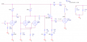
I am currently running with the circuit in attached schematic. Note a few minor tweaks (coupling cap between 1st, 2nd stage and current of 6BX7).
This sounds pretty darn good, actually.
The only difference between my current setup and my previous setup is the "layout" (aka rat's nest - DeathTrap2000(TM)) and possibly the value of the coupling cap between the 1st and 2nd stage. I don't recall if I used 1uF or 100nF before. But at least with this circuit, I'm not able to make the amp "lock" the output voltage -- except when the source follower bottoms out, of course.
/me like...
I'll listen to this for a while, then switch back to 5842-300B and see which I like better.
~Tom
Attachments
Tom,
Have you tried to raise the value of R9? With the FET you should be able to raise the impedance and take a load off of the driver tube to maximize the gain and linearity while at the same time extend the bandwidth with a smaller C4.
Since you are in "breadboard stage", have you considered a ccs under the fet? I want to build a test bed like this to see the implication in distortion and performance. I really don't know if it is good or bad, just curious.
Last edited:
Have you tried to raise the value of R9? With the FET you should be able to raise the impedance and take a load off of the driver tube to maximize the gain and linearity while at the same time extend the bandwidth with a smaller C4.
I have. And it seems there's an optimum value for R9 around 100~220 kOhm. Higher values actually cause more distortion. I'm not sure why...
Since you are in "breadboard stage", have you considered a ccs under the fet?
Someone else mentioned this a while back and I do plan to test it out. I'll report my results when done.
Right now I'm working on getting a high voltage regulator (LM317-based) to work. I figured that rather than using the darlington configuration used in the original circuit, I would use a MOSFET. But that causes trouble with instability. I need to order a few parts before I can get any further.
~Tom
Interesting on your measurements of R9. I'd be curious to understand why. Have to do some more reading I guess.
Along the same lines as what you are doing I was/am playing with a t7/FET/kt88. I use a CCS under the FET in this amp and have only diddled with a resistor. So this thread is very interesting. I was asked to build a 300b SET and I want to use a derivative of the power drive in that as well, almost identical to what you are doing.
Along the same lines as what you are doing I was/am playing with a t7/FET/kt88. I use a CCS under the FET in this amp and have only diddled with a resistor. So this thread is very interesting. I was asked to build a 300b SET and I want to use a derivative of the power drive in that as well, almost identical to what you are doing.
Last edited:
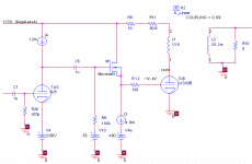
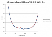
Attached schematic shows my test bench. I have performed comparisons between the 5842 and 6J5 in place of TU5. All measurements were done with an 8-ohm load at 1 W RMS output power.
The 5842 shows slightly higher THD than the 6J5 (0.1 percentage point higher at 1 kHz) - no surprises here. Comparing the source follower with resistive load vs CCS load reveals a marginal improvement in THD with CCS load. For resistive loading of the source follower, I replace I3 with a 22 kOhm resistor.
In terms of sound quality, the 5842 sounds harsher to my ears than the 6J5. I'm not sure if it's purely the difference in THD that makes for the difference - I kinda doubt that personally. But I don't know for sure. As far as the sound quality with resistive loading of the MOS source follower vs CCS load, the difference is fairly minimal. I think I currently favor the more open sound of the CCS load, but I'm comparing my experience now vs my listening experience late last night. So take this with a grain of salt. In terms of complexity and cost, the resistor wins hands down.
I should add that I'm now running off of a regulated HV supply. It's based on that ancient app note from National (LB-47 to be exact) and consists of an LM317 with an emitter follower in front to keep the voltage across the LM317 within spec. See page 361 in Morgan Jones, 3rd ed. or download the app note from National.com directly.
~Tom
Attachments
Last edited:
So I've done a little comparative listening now. Adding a CCS to the source follower rather than the resistor does cause an audible improvement. I wouldn't call it huge, earth shattering, but it's definitely worth taking IMO. The highs open up and seem to become more precise and the sound seems to decompress. I can't comment on any sound stage improvements as I'm listening in 2-channel mono (i.e. L+R).
In my final design I'll plan to have the CCS in there but probably leave room for the resistor so I can experiment once I have two channels running.
~Tom
In my final design I'll plan to have the CCS in there but probably leave room for the resistor so I can experiment once I have two channels running.
~Tom
Tom,
Your listening observations matchs mine with the ccs. I find that resistive loading is for lack of better word boring. With my set-up, the sound stage looses depth, in addition to the detail and clarity you reported.
Just guessing, but I would think the difference would show up in a FFT of a square wave.
I did some rudementary testing this weekend on the impedance of the gate bias resistor. In the case I mentioned above I found that the higher impedance actually improved my THD. In my set-up 500k was 0.07%, 750k was 0.05%, and 990k was 0.03% measured at 1kHz and 1Watt. Again it is a different output tube and amp.
Have you tried a higher bias current. I have mine set at 10mA per some suggestions. I havn't played with the value however.
Last edited:
In the case I mentioned above I found that the higher impedance actually improved my THD. In my set-up 500k was 0.07%, 750k was 0.05%, and 990k was 0.03% measured at 1kHz and 1Watt. Again it is a different output tube and amp.
Where are you measuring 0.03 % THD? Is that the THD of just the source follower? /me confused. A schematic would help...
Typical THD numbers for my amp are about 0.6 % THD+N for 1 kHz, 1 W, 8 ohm.
Have you tried a higher bias current.
I have not.
~Tom
- Status
- This old topic is closed. If you want to reopen this topic, contact a moderator using the "Report Post" button.
- Home
- More Vendors...
- Tubelab
- Limiting the grid current of PowerDrive