ffejgo: A few things...
Yes, variations in mains voltage will change your B+ voltage, so on a hot day with your neighbors all running their AC your B+ will be lower, since the voltage into your house will be sagging.
Here is one way to think of the PS:
with a choke input filter LC (no C4), you get 90% (.9 times transformer secondary voltage) for B+.
with a cap input filter CLC (using a cap at C4) you get roughly 141% (sqrt2 times transformer secondary voltage) for B+. It's usually a bit less than this due to series resistance voltage drops.
So with no cap in C4 you have 90% of transformer secondary voltage and with a typical value cap in C4 (say 10uf to 47uf or so) you get 141% transformer secondary voltage for B+.
Think of the above as a "spectrum" of possible voltages between 90% and 141%. As you reduce the value of the first cap below about 10uf or so, the B+ voltage will be reduced as you slide back from 141% to 90% since you will be heading from a CLC to an LC filter.
So installing say a 3uf, 2uf, or1 uf, etc cap in C4 will each reduce the B+ voltage. If you buy a few values of small film caps you can try these in a matter of minutes to dial in your desired B+ voltage. These small first caps also make life easier on your rectifier.
As Russ mentioned, LC filters need robust chokes.
Forgot to mention: I am using the Edcor XPWR131-120, an 80 MFD motor run, Triad C-14X choke, and the rest of the parts are stock per parts list.
Possible dumb question here: Are you using the 260V taps on the XPWR131?
Boywonder, Thanks for the reply.
I wired the OPT using Russ's previous thread:
The yellow wires are the 5V rectifier heater winding (TI-2 and TI-3). Same as Hammond. The brown wires are the 6.3VCT winding (TI-7 and TI-8). The white/brown is the center tap (TI-6). Hammond uses green.
The HT winding colors are a little goofy. The white wire is the HT CT, which goes to TI-1. Hammond is red/yellow. Which pair you pick for TI-4 and TI-5 depend on if you are using 45s or 300Bs. For 45s, use the black/red and white/orange pair. For 300Bs, use the red and orange pair. Doesn't matter which one goes on which terminal. (Thank you Russ for this post)
Just a few measurements with the 2 x 50ohm resistors still in series with the choke (May or may not be pertinent?):
T1-2: 360v
T1-3: 361v
T1-4 & T1-5: jumps between 1.17 and 1.54
R30: 340v with 22uf in C4 (Approx. ~130% of the 260v?)
R33 & R34: 75 (Noticed that my numbers are highter than on Russ's Pic)
45's Biased at 27
I don't understand the readings on T1-2 & 3. I thought they would be lower but nothing blew up so I guess they're ok.
I am going to change out the Triad Choke for the Hammond 158M (Costs less than a single 45 tube). I am also buying a couple of <5uf caps to titrate the voltage.
I can live with these higher voltages using my existing tubes but I want to roll pricier NOS 45 tubes and would hate to blow them because my voltage is well over their charted max voltage.
I will post my results after I recieve the parts. But if you any further suggestions please post them for me to read.
Thanks, ffejgo
T1-2: 360v
T1-3: 361v
The DC offset of the 5V winding is elevated to B+ by the rectifier tube. This is normal and is the reason why the rectifier tube heater must always have it's own winding. If you set your meter VAC and measure across T1-2/3, you should get about 5V.
T1-4 & T1-5: jumps between 1.17 and 1.54
Again, you need you measure VAC across these terminals, not relative to ground. One meter probe goes on T1-4 and the other on T1-5.
R30: 340v with 22uf in C4 (Approx. ~130% of the 260v?)
That's about right for a simple C filter. ~260 * 1.4 (sqrt of 2). It does seem like you are getting more than you should out of the B+ winding.
R33 & R34: 75 (Noticed that my numbers are highter than on Russ's Pic)
It just means that your tubes are more conductive than mine were and/or you are compensating for your higher B+. More bias is needed to get the plate current correct.
Those front two meters are across R18/29. The two red ones in the back are across R33/34.
I am going to change out the Triad Choke for the Hammond 158M (Costs less than a single 45 tube). I am also buying a couple of <5uf caps to titrate the voltage.
I can live with these higher voltages using my existing tubes but I want to roll pricier NOS 45 tubes and would hate to blow them because my voltage is well over their charted max voltage.
I will post my results after I recieve the parts. But if you any further suggestions please post them for me to read.
Thanks, ffejgo
Seems like a good plan.
I am going to change out the Triad Choke for the Hammond 158M (Costs less than a single 45 tube). I am also buying a couple of <5uf caps to titrate the voltage.
I will post my results after I recieve the parts. But if you any further suggestions please post them for me to read.
Thanks, ffejgo
Sounds good. A couple of thoughts....
If sometime in the future you want to try 300B's, the 158M won't have enough current capacity (100ma rating). It will be fine for 45's though.
The difference in DC resistance between the triad and the 158 M is 262-150=112 ohms. You may want to throw some resistors in series with the Triad to be sure that the resulting B+ does not end up too low with the 158M. Two of those Radio shack 50 ohm jobs in series will get you close.
EDIT: Re-reading your post above looks like you've already done that.........
Can you CAREFULLY measure the AC voltage from either the black/red or white/orange to the white wire with the amp powered up? (either end to the CT)
Last edited:
Russ,
I adjusted R18/29 to 30... This brought R33/34 to 70 (What is the optimal voltage for R33/34? I can't find a thread for this number)... and R30 back to 327v.
I can live here for a week or so untill the parts arive. The amp may be somewhat out of specs but it sounds sooo good.
Thanks!
P.S.
Across T1-4 / T1-5 is 564 VAC (Gotta remind myself not to touch those wires... I thought 350VDC was bad enough since I'd only get killed by half a wave). Just goes to show that "What you don't know can kill ya".
Can you CAREFULLY measure the AC voltage from either the black/red or white/orange to the white wire with the amp powered up? (either end to the CT)
I'll do this tommorow morning. They are easy to get to. Stripping a little off the end to do the test will not be a problem.
I'll do this tommorow morning. They are easy to get to. Stripping a little off the end to do the test will not be a problem.
Across T1-4 / T1-5 is 564 VAC
Looks like you've already measured what we are after, and as Russ mentioned, it's a bit high........
Can you measure the DC resistance from either end of the 260V winding to the center tap? You have to disconnect one of the leads to get a meaningful number; it should be around 30 ohms or so. I can post a PSUDII model of what you've got, and we can see what you'll need to drop the volts.
Ok here are my numbers:
Disconnected and exposed the 260 and 330 wires. Left white center tap connected to board. Should I have also disconnected the CT from the board???
To CT:
Red 377VAC
Orange 380VAC
These two together 766-780VAC (Jumped around)
To CT:
Black/Red 299VAC
White/Orange 299VAC
These two together 601 to 610VAC (Jumped around)
These two connected to board 560VDC (Normal hookup)
DC resistance Black/Red to White 37 (B/R Disconnected from board)
Thanks again for your guidence.
Foot Note: I had to remove my 100ohm resitors to do these. The R30 voltage climbed back to 344v (As expected)
Those are offloaded voltages, and will be high since they are unloaded. No need to disconnect the CT. When the amp is drawing current, the voltages will be a little lower (as you have already noticed).
37R seems reasonable.
What value caps are you using for C4 & C5?
The 560V "normal hookup" is with the amp idling with all of the tubes in place, correct?
37R seems reasonable.
What value caps are you using for C4 & C5?
The 560V "normal hookup" is with the amp idling with all of the tubes in place, correct?
Last edited:
C4 is 22uf
C5 is 150uf with a 80mdf Motor Run Cap in parallel
The 560v "Normal" is with the amp on and all tubes in place
Refering back to a previous question you had about changing to a 300b setup:
I think with the voltage problems I'm having with the 45's once I/we (Thank you for doing this) get it solved I'm sticking with the 45's. I can always just roll 45's. Plus the WAF is running lower. She expected Plug & Play...
Lowering C4 to around 2.2uf gets B+ down to about 287V using the existing triad choke and about 280V using the Hammond 158M.....
Do you have a load resistor connected across the speaker terminals when taking the voltage measurements?
Do you have a load resistor connected across the speaker terminals when taking the voltage measurements?
Attachments
Last edited:
No seperate load resistor... But the speakers are connected. 8 ohm (Klipsch Forte II).
I have to admit I don't know what the "ma" numbers mean? I did attempt the PSUDII program but couldn't figure it out.
A 287v R30 with the exsiting Triad would be great. I know that if I switch the Mullard 5AR4 out with a "New" store purchased rectifier or the other one I have on hand the 287v will drop by 10v or so. It's an option??? With the numbers you gave me I'll be able to save the $23.00 on the Hammond and not have to worry about taxing my system. The PT did hum louder and get 10 degrees hotter with those 2 x 50ohm resistors in series. Although there was no hum through the speakers. I did order 2.2uf caps Just have to wait for them to arrive.
I can't begin to express how very helpfull you have been. Thank you!
I have to admit I don't know what the "ma" numbers mean? I did attempt the PSUDII program but couldn't figure it out.
A 287v R30 with the exsiting Triad would be great. I know that if I switch the Mullard 5AR4 out with a "New" store purchased rectifier or the other one I have on hand the 287v will drop by 10v or so. It's an option??? With the numbers you gave me I'll be able to save the $23.00 on the Hammond and not have to worry about taxing my system. The PT did hum louder and get 10 degrees hotter with those 2 x 50ohm resistors in series. Although there was no hum through the speakers. I did order 2.2uf caps Just have to wait for them to arrive.
The load is a constant current (instead of the default resistive load in PSUD) the total current draw is:
27 ma for each 45 x 2=54 milliamps
12 ma for each 5842 x 2 = 24 milliamps
so 78ma total.
One advantage of the Hammond 158M is more henries, which will give you less hum, but if the hum is acceptable now, no worries.
Tubes have B+ "guidelines", so 270V-300V B+ is fine. The end result is the tube current times the B+ voltage roughly equals power dissipated as heat out of the tube. That's why Tubelab recommends backing off the idle current a bit when using higher B+ voltages. If you crank up the B+ and the current (within specs for the tube) the tube life will be shorter.
It's interesting that almost doubling the resistance of the choke only drops the B+ about 7V. That's because the current draw is relatively low.
Hi, first of all excuse me if this is not the correct thread, but here you're talking about supply, chokes, B+, so I try to present my question.
I've just built a TSE with 300B, as choke input I used a 200mA 7H 130 Ohm.
I understand that a higher resistance will have an impact in lowering B+, and that the power (200mA) must be correctly defined to match the tube's draw.
What I don't understand clearly is how a bigger or smaller Henries will affect.
I mean, for example, what would be the difference on B+ between these two :
Hammond 193L 5H 300mA 57 Ohm
Hammond 193M 10H 300mA 63 Ohm
Many thanks
Hi, first of all excuse me if this is not the correct thread, but here you're talking about supply, chokes, B+, so I try to present my question.
I've just built a TSE with 300B, as choke input I used a 200mA 7H 130 Ohm.
I understand that a higher resistance will have an impact in lowering B+, and that the power (200mA) must be correctly defined to match the tube's draw.
What I don't understand clearly is how a bigger or smaller Henries will affect.
I mean, for example, what would be the difference on B+ between these two :
Hammond 193L 5H 300mA 57 Ohm
Hammond 193M 10H 300mA 63 Ohm
Many thanks
Hi: The choke current rating does not necessarily need to match the tube's draw; it needs to equal or exceed the current draw. No harm in using a higher current rated choke other than size and $$.
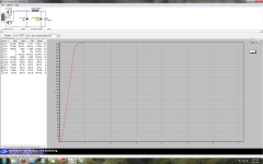
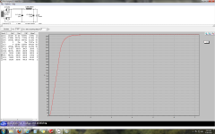
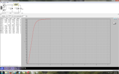
Using PSUD, the difference between 5H and 10H in a typical TubelabSE 300B PS is about 30mv of B+ ripple (60mv vs 30mv). The B+ voltage difference is less than a volt due to the 57 to 63 ohm DCR of the chokes.
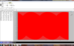
To get the B+ ripple voltage, just take the difference between the max and min voltages in the table at the left. Note I used a 4 second delay to get on the steady-state part of the B+ curve so that the voltage has settled out.
Attachments

Last edited:
I change the question, what criteria will make one decide to use a 5H vs a 10H choke?
Thanks
The PSRR (power supply rejection ratio) of the amp circuit. Circuits with high PSRR are more immune to B+ voltage ripple; ie they are less sensitive to the ripple voltage with respect to hum at the outputs (speaker terminals)......and of course $$ spent on the choke.
- Status
- This old topic is closed. If you want to reopen this topic, contact a moderator using the "Report Post" button.
- Home
- More Vendors...
- Tubelab
- Lowering B+ voltage