There are three people of varying skill levels building Simple P-P amplifiers using parts kits that I provided, and will have available after at least one of these builds are completed. The purpose is to find errors, and I have already received feedback from two of the builders, and only one has received their kit.
As many of you know the construction manual was assembled in several places, on 3 different computers, over a 6 month period, and it isn't even finished yet. For this reason I don't have 100% confidence that everything is perfect yet. It is hard for me to catch everything since I can build these things blindfolded.
Sherri assembled the first batch of parts kits when she was here for 10 days, and one tube socket was missing from all of the kits.
I am starting this thread for the beta builders to post their findings, photos, and general thoughts on their Simple P-P amps. I ask that this thread be reserved to a discussion of these three (and maybe more) beta builds only. I am reassembling my 6CW5 amp, and I may post that build either here or in another thread (I haven't decided yet), but I ask that other builders start their own thread.
So far I haven't found any real errors on the site. One thing I would suggest for those that order the kit is grab a couple of pieces of paper and label each part with their value and the component number for the board and just adhere them to the paper with some tape. I found this useful with the resistors mainly. The capacitors aren't that difficult but misplacing a resistor could be pretty easy especially the 1/4 watt ones. As I was stuffing the board it was easy enough just to grab it off the paper and place it on the board. I think the resistors took me 15 minutes to place and solder.
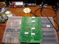
Had a bit of time to stuff the resistors this evening. I followed along with the bottom assembly procedure and didn't notice any errors, though I put resistors on both sides for various reasons. The only comments are really for beginners:
Swapping R2 and R4 seems like the easiest error to make. You do mention it at the beginning, but maybe it's worth using a slightly different R2 value?
It might also be worth it for soldering novices not to solder joined pads until both parts are in (R110 and R111, for example).
Identifying resistors by color code is a good exercise, but the precision resistors might be confusing for some since it is not always obvious which way to read them (1.00k, for example). I've also seen some (not these) were it is hard to tell what the colors are because the resistor bodies are so dark (red looks like brown, etc).
Attachments
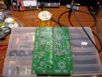
The board is stuffed. A few discrepancies in the parts list for the caps:
C100/C200 are listed as 1000uF@16V but the supplied parts were 1500uF@6.3V. Looks to be the bypass cap for the input tube section cathode, so 6.3V should be fine I expect. Might match the cap in the pictures, but it's hard to tell.
C102/C202 are listed as 47uF@450V but the supplied parts were 82uF. Looks like it matches the picture, though.
Attachments
I was a little weary of standing the noval sockets on their toes to align them with the octal socket. The tips barely reached the top surface of the PCB. I opted to seat them fully instead. I remember doing this for the SSE and TSE, but I don't remember them being so close to the edge. Maybe it's because I used Belton noval sockets on those?
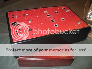
Well I have pretty much got my chassis all built up. The board is stuffed with exception to one socket and I have all the transformers in hand. I still have to reinforce the aluminum top plate and add some brackets so I can keep it mounted to the wood base. Does anyone have any ideas for a decent color for the top plate. I got a whole bunch of free aluminum sheets from a guy building a fish house so the red wasn't really my idea. It is starting to grow on me a little but red really isn't my color.
C100/C200 are listed as 1000uF@16V but the supplied parts were 1500uF@6.3V. Looks to be the bypass cap for the input tube section cathode, so 6.3V should be fine I expect. Might match the cap in the pictures, but it's hard to tell.
C102/C202 are listed as 47uF@450V but the supplied parts were 82uF. Looks like it matches the picture, though.
The first 3 amps I built, and the first few parts kits that Sherri put together used the values that you have. They were based on components that I had in stock. I have since ordered 50 sets of exactly the parts shown on the parts list. I retrofitted 2 of my boards which are being used in the dual mono Simple PPP amp. I have also built 2 more boards, which have been tested, but not assembled into amps yet. Many of the pictures were taken using boards built last year.
I was a little weary of standing the noval sockets on their toes to align them with the octal socket. The tips barely reached the top surface of the PCB.
The board with the tube sockets standing on their tip toes has been doing duty as my tube tester / tube matcher. I have stuffed about 50 6CW5's through this board, often multiple times in order to come up with 6 sets of reasonably matched tubes. No issues were seen with the sockets.
George any idea on what size fuse would be suitable for the 6CW5 version of this amp would be.
I have a 2 amp in mine because thats what I could find. I would think that a 1.5 or 1.6 amp slow blow would be a better choice. A one amp doesn't work. It will sometimes blow at turn on.
Does anyone have any ideas for a decent color for the top plate.
Grey hammerlite ?
Covers scratches well, gives a nice vintage look, and easy to handle
I'll put it on a "proper" breadboard sometime soon and try it out in the other room on some good speakers. I have a power transformer or two for this thing somewhere. I know the one from the abandoned "Bevois Valley" amp will work, if I can find it.
I just thought you might like to know that it works just fine. No issues at all.
I just thought you might like to know that it works just fine. No issues at all.
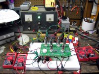
Here is the amp on a breadboard. I found a Hammond 373CZ, which will do 650VCT @ 173mA. Since they have a reputation, I brought it up on a variac and could not get to line level without reaching scary plate-to-cathode voltages. I stopped at about 77% (85% is line-level) in the attached picture. It shows B+ on the left, the HT winding at the right-front, and the plate-to-cathode voltage on V201 on the right-rear meter. The primary is wired for 120V operation. It seems that this transformer is too hot for this amp. I wanted to point out that at least in my case, 615VAC under full load is the max I would put into this thing. The XPWR131 is probably not a good choice either. 600VAC seems like it would be safer.
Comments after being attached to my 98dB speakers: the amp has some 120 Hz buzz, but I am not surprised. I think the Simple SE was similar before I put the choke on. The amp also has some hiss with the inputs shorted, but not much. Less than my ST70 I would say. However, the amp has a lot of GAIN. I hear lots of noise from my SqueezeBox that I don't hear with my other amps. I had to turn the SB volume way down. It is directly connected, so it may be quieter through a real volume control.
I didn't listen to it long...just a few tracks. The noise from the SB was bothering me. I hate audio adjectives, but my initial impression right off the bat was that the amp sounded "fast". A couple of live tracks I listened to had good detail and good imaging, so I was happy about that (the ST70 lacks both). The bass felt laid-back, which surprised me a little. George, I am using the black and yellow wires on the OPT secondaries as the 8-ohm taps. The other two wires are left disconnected. Is this right?
Attachments
OK, that might explain the weak bass. Also, it occurred to me that I don't have the NFB connected, so that would explain at least some of the excessive gain. I have two little blue caps that were in the bag. I can just try those and see what happens.
Need to hook it up to the scope next.
Need to hook it up to the scope next.
Green/yellow = 8ohms
Yellow = 4ohms
Green= 16ohms
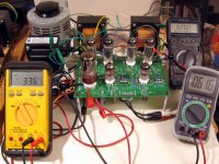
Looking good russ. I need to grab myself some more meters.
This is correct. Assuming an 8 ohm speaker, use the black and green/yellow wires with EL84's (6600 ohm load) and use the black and green wires for 6CW5's (3300 ohm load). The yellow wire does not get used. These OPT's are somewhat ugly but the cores seem to be a common size. This allows the reuse of end bells salvaged from other transformers. I ripped the power transformers and tubes from several HP audio oscillators that had been sitting outside in the rain for years. The tubes (6CW5's) have found use in my amps. The end bells from many of the power transformers have found their way to these OPT's and a repainted pair can be seen in the 6CW5 amp on my home page.
Make sure that the black wires are connected to the grounded feedback terminals (one terminal block is backwards from the other). Swap the blue and brown wires as needed to insure negative feedback.
600VAC seems like it would be safer.
I have a 600 VCT Hammond in my EL84 amp. I don't remember the number right now. I am at work. This is a conservative design that works with all "EL84" type tubes, and makes about 15 WPC.
If you like to experiment you can try this. Connect the red wires from the OPT's to the L1 terminal that goes to the input filter cap. Increase the value of R1 (about 2K) until the voltage for the rest of the amp is in the 300 to 330 volt range. What you are doing here is running the plates of the EL84's at 350 volts or more ( I have been to 410 volts with JJ's) and the rest of the amp (including the EL84 screens) at a lower voltage. Obviously this only works in pentode mode. I have found that this hookup generates some extreme power levels (up to 30 WPC) with very low distortion. This is above the spec for EL84's so try this at your own risk. It is within the spec for 7189A's (not 7189's), which are extremely rare tubes. Much of what is being sold today as 7189A's are relabled Russian 6P14P's which will MELT at these voltages. Trust me, I know this!
I hate audio adjectives, but my initial impression right off the bat was that the amp sounded "fast".
I have come to the same conclusion. This trait has been shared with several of my other amps including the "red board" and the 300Beast. So far the only thing these amps have had in common is the OPT's. I have ripped one of these transformers apart to discover that they are constructed completely wrong by audiophile standards. There is NO interleaving at all and the core material looks identical to my Schumaker battery charger. I have the spec sheet somewhere. They are rated for "80 VA" from 80 Hz to 4 KHz. Yet they sound and measure quite well. I have also proven that they will pass over 200 watts at 1KHz, but no more than 20 watts at 25Hz.
Add a 500 pF or so compensation cap (the one that gets left out during the build) with these OPT's and EL84's. This will remove the "edgyness" from the high frequencies.
...and a repainted pair can be seen in the 6CW5 amp on my home page.
Thanks. I kind of like the fact that they are ugly. Having some rat-rod design thoughts....
")
I have a 600 VCT Hammond in my EL84 amp. I don't remember the number right now. I am at work. This is a conservative design that works with all "EL84" type tubes, and makes about 15 WPC.
Probably the 272JX you mention in the manual.
I have been to 410 volts with JJ's
These are Sovtek EL84Ms. They supposedly can handle "300-500" volts to the plate and screen, though empirical evidence about these tubes says otherwise. The envelopes are slightly wider than normal EL84s, but so are the other "normal" Sovteks. At 320V, I did not see any plate or screen glow. I may try ramping things up later to see when they start to become upset.
Connect the red wires from the OPT's to the L1 terminal that goes to the input filter cap. Increase the value of R1 (about 2K) until the voltage for the rest of the amp is in the 300 to 330 volt range.
Ah yes, I remember you mentioning something about this in your other thread. Sounds like fun...I will have to try it and see how far I can go. I plan on thrashing this amp a bit more than normal (well, for me anyway).
They are rated for "80 VA" from 80 Hz to 4 KHz. Yet they sound and measure quite well. I have also proven that they will pass over 200 watts at 1KHz, but no more than 20 watts at 25Hz.
Thanks, I was going to ask if you had any specs on these. 80VA...LOL. True mark of a power transformer company. I generate some Bode plots and see what I get as well.
Add a 500 pF or so compensation cap (the one that gets left out during the build) with these OPT's and EL84's. This will remove the "edgyness" from the high frequencies.
I think the caps in the bag were 880-puff. Any thoughts on the gain? This thing has more gain than my ST70! I'll have to see what the gain really is under test.
I think the caps in the bag were 880-puff. Any thoughts on the gain? This thing has more gain than my ST70! I'll have to see what the gain really is under test.
I put some 880pF caps in the first few bags. The gain will drop about 6 db or so when the feedback is hooked up. I don't have absoulute measurements here, but is is similar to the Simple SE. My Wally mart DVD plaver drives it to full tilt at about 3/4 throttle on the volume knob. Some softly recorded CD's can be turned all the way up.
I generate some Bode plots and see what I get as well.
With the GNFB connected, a 510 pF compensation cap, and power in the 1 watt range the 3 db points were something like 11 Hz and 60 KHz. I remember posting the 10KHz square wave picture on the forum somewhere. Not too bad for an "all wrong" OPT.
Found it, post #5:
http://www.diyaudio.com/forums/tube...-square-wave.html?highlight=10KHz+square+wave
- Status
- This old topic is closed. If you want to reopen this topic, contact a moderator using the "Report Post" button.
- Home
- More Vendors...
- Tubelab
- Simple P-P "beta builders" thread