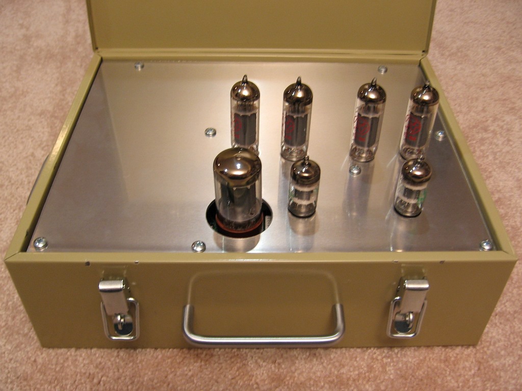
Hehe...yep. This amp was an unexpected entry into the tube amp work queue, but I wanted to get it done. I wanted a tube amp in the garage, but I didn't want to leave it out there. Something "portable" and quick to assemble (yeah right). I found this lock box that we weren't using...at least not anymore, LOL!
If I had known this was a double-walled box with fiberglass insulation in between, I'd have found something else. Glass has a way of dulling drill bits! Not to mention the dust....
If I had known this was a double-walled box with fiberglass insulation in between, I'd have found something else. Glass has a way of dulling drill bits! Not to mention the dust....
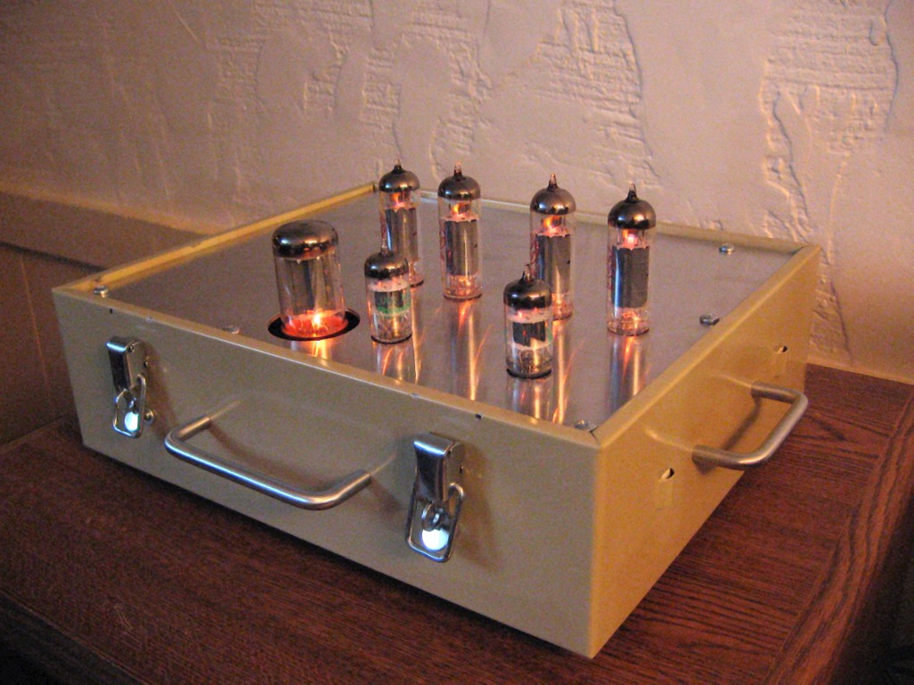
I like the lock box idea. Would look pretty good with two handles on the top plate and take off the one in front..........now you have given me some ideas on how to modify one. I was also thinking of taking an old ammo can and placing this amplifier in there.
Is there a safety feature that keeps the cover from closing if the tubes are not removed?

Hehe...yeah. I'll probably end up cutting holes in the lid so the tubes can be put in with it closed or a big square opening so it can be closed during operation.
Seriously, Russ, that is a very cool departure from the same old wooden plinths etc. If you look around the 'net on DIY sites, you see the Euro and Asian cats come up with some unusual chassis ideas. I only have the common hand tools so fancy stuff is out of the question at my workshop.
Last edited:
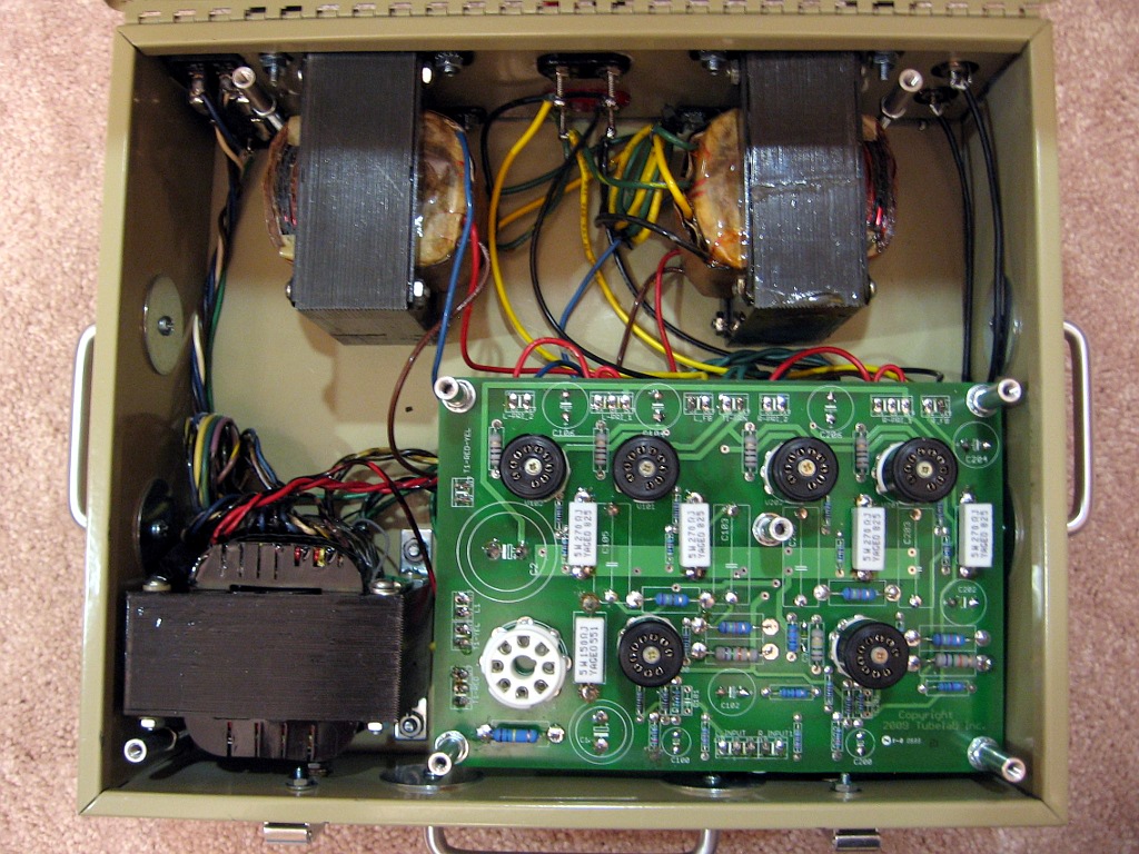
Thanks all. 🙂 It's technically not finished yet. The only ventilation right now is
around the recessed rectifier and there is no air inlet anywhere. At this point I just want to see where the hot spots are.
For the lid, my other thought is to remove the hinge pin and just allow the lid to be taken off entirely. The problem with cutting holes is that it is also double-walled with fiberglass between.
Very innovative Russ, love it. Great engineering there. This thread is supposed to be for beta builders only, so I'm a bit reticent to post or comment or ask questions here.
Ian.
Ian.
Russ, when you posted the picture of the box, and nothing else, I thought that it might make a good chassis. Now I see that you have done it justice.
I have been working on an unusual cabinet for an unusual amp. Those ugly OPT's and an Antek toroid will be plainly visible (If I don't change my mind again).
I enrolled in an evening wood shop class at a local high school so I could use their shop. I used rather basic tools for this build. I did use a table saw though.
Seriously, Russ, that is a very cool departure from the same old wooden plinths etc. If you look around the 'net on DIY sites, you see the Euro and Asian cats come up with some unusual chassis ideas.
I have been working on an unusual cabinet for an unusual amp. Those ugly OPT's and an Antek toroid will be plainly visible (If I don't change my mind again).
I only have the common hand tools so fancy stuff is out of the question at my workshop.
I enrolled in an evening wood shop class at a local high school so I could use their shop. I used rather basic tools for this build. I did use a table saw though.
Thanks again, all. The top plate got pretty hot, but it took a good hour or two to get that way. So some additional air flow would probably improve things sufficiently. I'll put a thermocouple inside next to see how hot it really gets under the PCB. All the power resistors were relocated to the top.
I used a drill press to do the top plate, but the rest was done with a center punch, a hand drill and a dremel. The drawer handles and pull latches were added since the handles it came with were flimsy plastic and lock is no longer functional.
I used a drill press to do the top plate, but the rest was done with a center punch, a hand drill and a dremel. The drawer handles and pull latches were added since the handles it came with were flimsy plastic and lock is no longer functional.
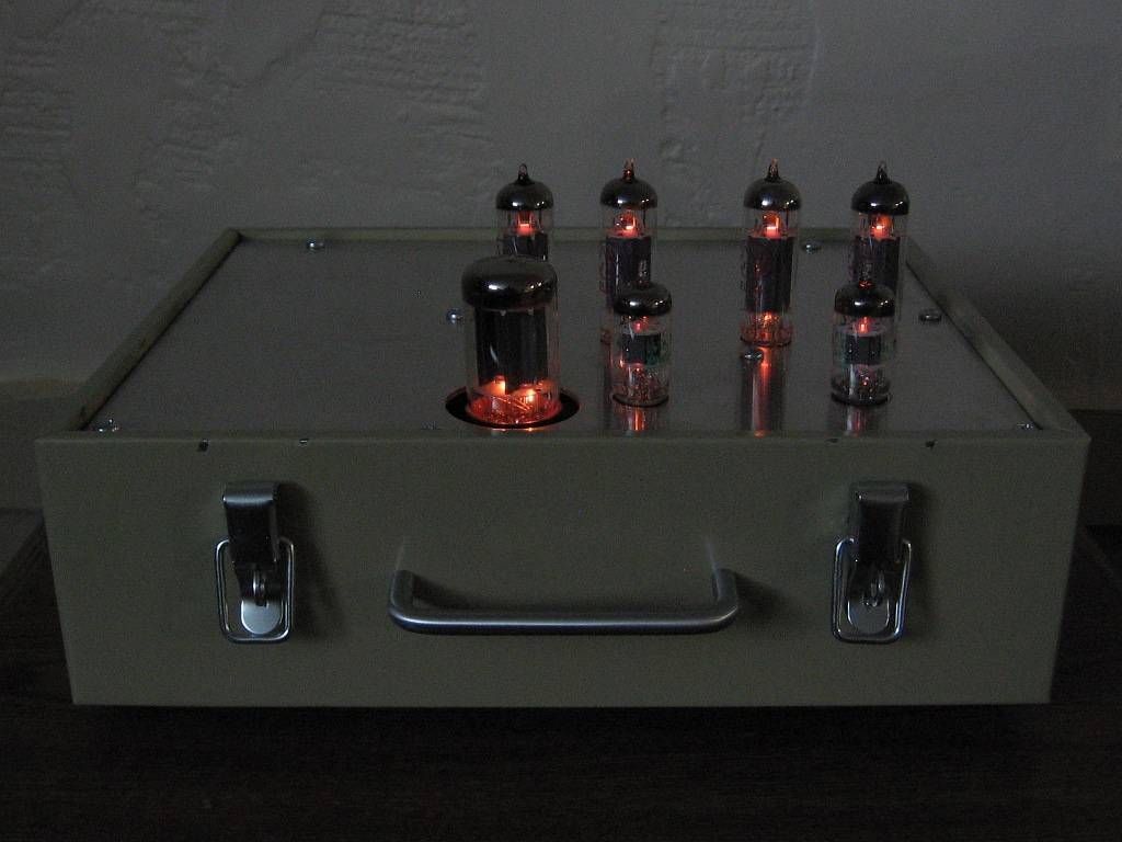
Obligatory glam shot.
Listening impressions...well I've got a few hours on it now but no serious listening yet. The amp sounds fast like it did on the breadboard and has good bass response. It could do with a bit of feedback, I think. Right now it has no caps in place.
It has noticeable hum and a bit of buzz on my main system, which has 97dB speakers. I didn't really notice it in my shop. The buzz is probably due to the fact that I eliminated the choke and went with the 150 ohm resistor. There is room in the chassis for a choke and I'll add it if needed. I'm guessing the hum is being induced by the close proximity of the power transformer to the PCB. The iron has no bells and the chassis is steel. Being a Hammond...well.... I'll short the inputs and see what happens.
Shorting the inputs make the amp quiet except for a little bit of buzz. Totally killed the hum, so there is hope. 🙂
- Status
- Not open for further replies.
- Home
- More Vendors...
- Tubelab
- Simple P-P "beta builders" thread