Dear George,
I am assembling the TubelabSE with the big components on the lower side of the board. I assembled the capacitors, but I am not sure about the semiconductors. How hot do they get ? I would not like to cook the board putting them down.
By the way I took some pictures of the boards, and I will be happy to send them to you if you want to use them for documentation.
I already assembled the Simple SE, and everything is working fine. A couple of questions: what happen if I switch on the diodes rectification by mistake when the rectifier tube is installed ?
What id behind the choice to lift the heater ?
Best Regards,
Davide
I am assembling the TubelabSE with the big components on the lower side of the board. I assembled the capacitors, but I am not sure about the semiconductors. How hot do they get ? I would not like to cook the board putting them down.
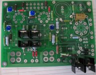
They get fairly hot, especially the MOSFETs. I originally built my TSE this way. Note that when you mount them on the bottom, you have to turn them around such that the heat sink legs don't line up with the PCB. If you turn them around and space them away from the board carefully to clear some of the resistor leads that are right there, it can be done. The 5-lead regulator cannot be done this way and the only way to do it is to dnagle it off the PCB line I did here:
http://www.diyaudio.com/forums/tube...nother-tubelab-se-sorry-long.html#post1775288
I already assembled the Simple SE, and everything is working fine. A couple of questions: what happen if I switch on the diodes rectification by mistake when the rectifier tube is installed ?
Nothing. The silicon diodes have lower forward drop, so they will take the load away from the tube. You will just be burning power running the tube heater for no reason. I have a lot of capacitance in the supply on my SSE and it takes several seconds for the B+ to settle when switch from silicon to tube rectification.
I am thinking of putting them up, I don't like to have them down, they will heat the electrolitic caps.
So I am thinking of using something with the shape of a cilinder between the chassis and the tube socket. My question now is: all the 300B have the same diameter for the base ? if the socket is installed lower than the plate of the chassis, how big should the hole be ?
Is there any way to electrically isolate the heatsink from the semiconductor, so that I don't have B+ on them ?
Thanks,
Davide
My question now is: all the 300B have the same diameter for the base ? if the socket is installed lower than the plate of the chassis, how big should the hole be ?
They are roughly 1-3/8", so you would want to allow for at least 1.5". You'd want to go considerably more if you are hoping for some convection.
Is there any way to electrically isolate the heatsink from the semiconductor, so that I don't have B+ on them ?
Yes. There is a classic mica wafer and white grease approach or you can go with the fancy thermal pads that aren't as messy and often perform better. Get the thickest ones, if that is the case.
If the heatsink is anywhere exposed that would allow someone to touch accidentally, then I would isolate with mica/grease or a silpad and then bond the sink to ground.
For mine, to pull the heat away from close proximity to the caps, I made a heat sink plate out of 1/8" aluminum plate. The chassis stil gets warm, but the intense heat is further away. Also be wary of the 5W, 10k (R6) resistor, it gets extremely hot as well. Keep it as far away from the board/components as possible.
For mine, to pull the heat away from close proximity to the caps, I made a heat sink plate out of 1/8" aluminum plate. The chassis stil gets warm, but the intense heat is further away. Also be wary of the 5W, 10k (R6) resistor, it gets extremely hot as well. Keep it as far away from the board/components as possible.
About the grid stoppers
I'm planning on running wires from the tube socket holes on the board to chassis mount sockets. Being able to insert the stoppers at the sockets should negate the downside of socket extensions?
Have I failed to anticipate any other catastrophic or annoying issues?
I'm planning on running wires from the tube socket holes on the board to chassis mount sockets. Being able to insert the stoppers at the sockets should negate the downside of socket extensions?
Have I failed to anticipate any other catastrophic or annoying issues?
Getting cold feet on wiring the tube sockets and have decided to simply put them on the revrse side. If I add a nice long piece of 1/8" aluminum bar to the doubled up heat sinks at the edge of the board would that keep things cool enough?
Attachments
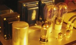
It will help. All I have done to mine so far as the chassis comes together is put this little 1" angle stock on. It's enough to prevent thermal shutdown with 300Bs:
They key is airflow. Adding a larger sink to an enclosed chassis will delay the inevitable. If the bar attaches to the chassis somehow, it should be fine.
I hope you aren't planning to mount the PCB upside down. The tube sockets will have their pins swapped. It won't matter for the heater, but having the grid and plate pins swapped will be bad.
Filament Heat Sink Alternative
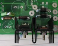
Here is another possibility. I know George didn't have much luck bending the 5pin regulator leads, but it can be done carefully. In the attached photo I had an extra heat sink laying around so I cut through the top plate and exposed it. It is electrically isolated with mica and grease. The sink is bonded to chasis ground in case the insulators break down.
For the FETS and CCS I used 1/8th inch plate similar to rknize. The key is to have some airflow in the chasis. Otherwise, as I found out, the FETS WILL die.
Attachments
I hope you aren't planning to mount the PCB upside down. The tube sockets will have their pins swapped. It won't matter for the heater, but having the grid and plate pins swapped will be bad.

OK, between your last post and finally placing sockets and tubes on the board, I get it. I had the wild-eyed idea of wiring the sockets because I have this phobia about amps whose sockets are so buried it's necessary to grasp the tube by the bulb.

An externally hosted image should be here but it was not working when we last tested it.
1 1/4" stand-offs will expose the bases of all but the 9-pins and those are much tougher IME than the big guys.
Thanks for that!
1 1/4" stand-offs will expose the bases of all but the 9-pins and those are much tougher IME than the big guys.
Use a "socket saver" to boost the height od the 9 pin tubes.
AES (Antique Electronic Supply) # P-ST9-900
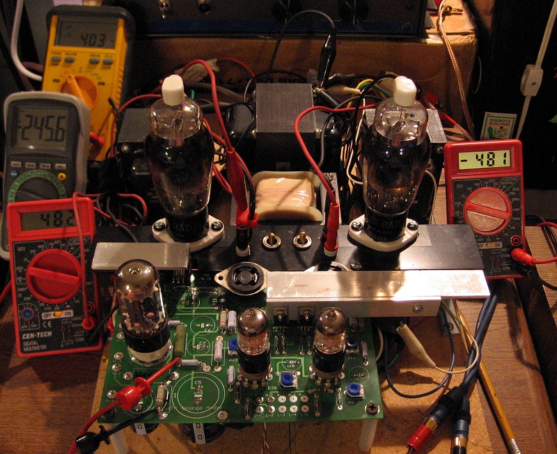
Just for the records, I measured the temperature of the heat sinks with a thermocouple.
The mosfet are at 110 C and the CCS at 90 C, with the standard heat sink. The probe was between the two and the board is working without chassis.
I don't think is a goos idea to have them under the board. :-(
D.
The mosfet are at 110 C and the CCS at 90 C, with the standard heat sink. The probe was between the two and the board is working without chassis.
I don't think is a goos idea to have them under the board. :-(
D.
Not without pulling the heat away from the area with a large heat sink of some sort, no. Sounds similar to the measurements I made with the same setup. I ended up putting them back on top after playing around with the chassis design, though either way would have been fine, thermally.
- Status
- This old topic is closed. If you want to reopen this topic, contact a moderator using the "Report Post" button.
- Home
- More Vendors...
- Tubelab
- Tubelab SE inverted assembly