9K won't hurt a bit , maybe just a very very slight power loss to the new benefit of lower distortion. They do have UL which you might like, but they are only 10W & do look really small.
This will have an affect on the Bass and possibly the Highs. Possibly if you ran them in Triode mode for less than 10W/CH they may work better. If they are only laking in the low end you could run a subwoofer/amp setup. If you can afford a bigger one you probably would be happier IMHO. Output Transformers are really what makes a tube amp sound good.
Ask how many watts are the ATH131 rated for? More than double the price, but may have more interleaving and much bigger cores.
Maybe also check with EA Sowter, Amplimo, AE Europe, & Lundahl.
If you could find a ratty Dynaco SCA-35 over there all the transformers would be great. Those Z-565 OPT transformers are a great STD to look for.
Randy
Last edited:
I would like to know what switches do i need to wire the cfb and mode for the spp. Do I need the 'on-off-on' or 'off-on-on'?
Progress is coming along slow but sure. I'm using Kiwame, Mills and Takman resistors, Audytechnika coupling Tru Copper caps and Elna electrolytic ones.
As for Primary Tranny i'm opting for a Hammond 372hx/fx. Any recommendations on this? OPt's for me are looking like Hammond again other brands like Triode arent redily available in the UK. Again any recommendations would be welcomed.
I want to spend some time and effort on the enclosure and was considering a anti-vibration mounts, illuminated power switch and even a motorised volume. Can I use the 6.3voutput to run the LEDs?
No such diagrams exist from George, I'm afraid. If my memory serves, an SPP builder on this forum made some diagrams.
Keep in mind that the SPP has slight different configurability options than what the SSE has. You can put a switch on the screens to swap between triode and pentode/UL, but there is no cathode-feedback option on the SPP. There is a global feedback loop, but that is largely set-and-forget once you have it the way you want (OPT-dependent). I'm not sure if anyone is actually running the SPP setup as triodes. If you wanted to do it, it would be the same as SSE. The "common" would connect to the PCB with one pole connected to the UL feedback of the OPT (or B+ for pentode) and the other pole would go to the tube plate.
Keep in mind that the SPP has slight different configurability options than what the SSE has. You can put a switch on the screens to swap between triode and pentode/UL, but there is no cathode-feedback option on the SPP. There is a global feedback loop, but that is largely set-and-forget once you have it the way you want (OPT-dependent). I'm not sure if anyone is actually running the SPP setup as triodes. If you wanted to do it, it would be the same as SSE. The "common" would connect to the PCB with one pole connected to the UL feedback of the OPT (or B+ for pentode) and the other pole would go to the tube plate.
No such diagrams exist from George, I'm afraid. If my memory serves, an SPP builder on this forum made some diagrams.
Indeed there were some excellent diagrams showing terminal strip connections for all 3 possible configurations - which I thought I'd squirreled away on this PC, but apparently not. By the time I find them, they may surface from other sources - perhaps even earlier this lengthy thread.
As my recycled vintage Scott OPTs lacked U/L taps, my original configuration was triode - sounded very nice, but no more power than a DIY hack job I already had on hand, so I soon reconfigured to Pentode.Keep in mind that the SPP has slight different configurability options than what the SSE has. You can put a switch on the screens to swap between triode and pentode/UL, but there is no cathode-feedback option on the SPP. There is a global feedback loop, but that is largely set-and-forget once you have it the way you want (OPT-dependent). I'm not sure if anyone is actually running the SPP setup as triodes.
\If you wanted to do it, it would be the same as SSE. The "common" would connect to the PCB with one pole connected to the UL feedback of the OPT (or B+ for pentode) and the other pole would go to the tube plate.
Indeed there were some excellent diagrams showing terminal strip connections for all 3 possible configurations - which I thought I'd squirreled away on this PC, but apparently not. By the time I find them, they may surface from other sources - perhaps even earlier this lengthy thread.
As my recycled vintage Scott OPTs lacked U/L taps, my original configuration was triode - sounded very nice, but no more power than a DIY hack job I already had on hand, so I soon reconfigured to Pentode.
\
I think the drawings referenced above might have been from Ian444? - but I can't recall whether they were posted on the forum, or sent privately - and a quick search on both home and work hard drives doesn't find them yet.
Of course, this may already be moot
edit: try here (Post 353)
http://www.diyaudio.com/forums/tubelab/148694-tubelab-simple-p-p-36.html#post2568175
yes it was Ian - thanks again
Last edited:
If you are looking at modern production, there are really only two types.
JJ makes an EL84 that is pretty tough. My SPP has a bit too much B+, but the JJ tubes laugh it off.
There are the ones made by New Sensor, which are all based on the Russian 6P14P design. They are marketed by New Sensor under a variety of names, brands, and prices. If it is new production and not JJ, it's probably New Sensor. They generally work fine until you push a bit too hard on the B+ front. Their screens can't handle voltages much over 300V. The 372JX should put you close to the edge, but still safe. I can't run these in mine, which uses a 373CZ.
Adding fixed bias, even with Dave Gillespie's fixed bias EFB Mod would enable you to get the tubes dissipation to the safe level with any production tube. It can be added to any EL-84/7591 PP amp.
Dave's Lab
Dave's Lab
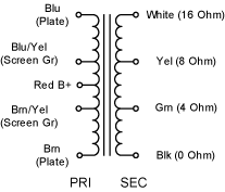
Well, this is the wiring diagram for the Hammond 1650FA OPT:

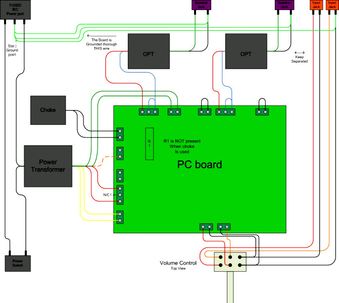
Each channel on the SPP has 3 sets of terminals for the OPTs. So for example, from left to right along the back of PCB:
Left Channel
Right Channel
Please note that L_FB and R_FB are mirrored! Also note that if you do decide to use feedback (by installing C101/201), you may need to swap the PRI_1 and PRI_2 secondary connections on each channel to get the right phasing (leave the red wire where it is). I can't remember if I had to or not. You'll know if it's wrong if you get loud squealing out of your speakers with feedback connected.

Each channel on the SPP has 3 sets of terminals for the OPTs. So for example, from left to right along the back of PCB:
Left Channel
- L-PRI_2
- 2 - V102 screen - primary blue/yellow wire
- 1 - V102 plate - primary blue wire
- L-PRI_1
- 3 - V101 screen - primary brown/yellow wire
- 2 - V101 plate - primary brown wire
- 1 - primary red wire
- L_FB
- 2 - Ground - secondary black wire
- 1 - Feedback - secondary (green, yellow, or white)
Right Channel
- R-PRI_2
- 2 - V202 screen - primary blue/yellow wire
- 1 - V202 plate - primary blue wire
- R-PRI_1
- 3 - V201 screen - primary brown/yellow wire
- 2 - V201 plate - primary brown wire
- 1 - primary red wire
- R_FB
- 2 - Feedback - secondary (green, yellow, or white)
- 1 - Ground - secondary black wire
Please note that L_FB and R_FB are mirrored! Also note that if you do decide to use feedback (by installing C101/201), you may need to swap the PRI_1 and PRI_2 secondary connections on each channel to get the right phasing (leave the red wire where it is). I can't remember if I had to or not. You'll know if it's wrong if you get loud squealing out of your speakers with feedback connected.
- Home
- More Vendors...
- Tubelab
- Tubelab Simple P-P

