How do these look?
Dale 23 Step Attenuator 2-Chl Volume potentiometer 50k | eBay pt=LH_DefaultDomain_0&hash=item4aae0012c6
http://www.ebay.com/itm/DALE-4X24-S...157?pt=LH_DefaultDomain_0&hash=item336af0fff5
Last edited:
Perhaps George will find a way to correct this in the future. And perhaps he did try it, but couldn't get the PCP to allow for it.
I don't claim to be artistic, but I do like things that are symmetrical. I am foremost an engineer and I design things for function first, then fit the form around them.
Of course the rectifier tube is always the odball since it is usually a different size than the other tubes. This is the case in most amplifiers. The logical place to put the rectifier is on the centerline of the PC board to preserve symmentry. From an engineering standpoint this is about the worse place to put it.
The rectifier and surrounding circuitry handles hundreds of volts of 50 or 60 Hz. It also passes high currents in short bursts. The rectifier must be kept as far as possible from the input circuitry to avoid hum. The traces to and from the rectifier must be carefully routed to create the PC board version of a single point ground (SSE and TSE) or a ground bus (SPP).
The only place to put the rectifier electrically that would satisfy the symmetry criteria would be in the center of the back edge of the PC board with two output tubes on each side. The circuitry supporting the rectifier tube must be kept in its own island of ground with only one ground connection to the rest of the PC board at the negative terminal of the output filter capacitor. Designing a PC board for a tube amplifier is actually a lot like making a point to point version. Fortunately it only has to be done right once. Every exact copy of the correct design will be the same and hum free.
Placing the rectifier in the center of the back of the board will make the board a lot wider. A wider board costs more to manufacture and triggers an oversize charge with some PC board vendors. It also makes it harder for the finished amplifier to be built with the golden ratio without making it rather large.
Up until recently the active screen size of all TV sets and most computer monitors was 4:3 which is 1.33:1, HDTV is 16:9 which is 1.77:1. It used to be common to put speakers on the sides of 4:3 monitirs to make them wider. Now the speakers are on the bottom edge to make them taller.
I am thinking of finding a way to elevate the tube sockets from the board.
I have made stilts from brass tubing with heat shrink over it.
Attachments
George I bet that board would support 7591 types as easy to drive. Just a few PS mods. Bigger trans would only cost a few $ more. Fixed bias would be needed for sure with modern production tubes from what I've read. Maybe Dave Gillespie's EFB mod would be a low cost simple way of doing it.
What do you think.?
Have you ever tried the 6973 as it's supposed to sound great?
Of course parallel EL84's could be done with other off board in the same way or use 2 boards.
Keep up the great mods!
Regards,
Randy
What do you think.?
Have you ever tried the 6973 as it's supposed to sound great?
Of course parallel EL84's could be done with other off board in the same way or use 2 boards.
Keep up the great mods!
Regards,
Randy
I don't claim to be artistic, but I do like things that are symmetrical. I am foremost an engineer and I design things for function first, then fit the form around them.
Of course the rectifier tube is always the odball since it is usually a different size than the other tubes. This is the case in most amplifiers. The logical place to put the rectifier is on the centerline of the PC board to preserve symmentry. From an engineering standpoint this is about the worse place to put it.
The rectifier and surrounding circuitry handles hundreds of volts of 50 or 60 Hz. It also passes high currents in short bursts. The rectifier must be kept as far as possible from the input circuitry to avoid hum. The traces to and from the rectifier must be carefully routed to create the PC board version of a single point ground (SSE and TSE) or a ground bus (SPP).
The only place to put the rectifier electrically that would satisfy the symmetry criteria would be in the center of the back edge of the PC board with two output tubes on each side. The circuitry supporting the rectifier tube must be kept in its own island of ground with only one ground connection to the rest of the PC board at the negative terminal of the output filter capacitor. Designing a PC board for a tube amplifier is actually a lot like making a point to point version. Fortunately it only has to be done right once. Every exact copy of the correct design will be the same and hum free.
I guess this gets us back to the need to just go with SS rectification, and eliminate the rectifier tube. The SS rectification would still be where it is on the pcb, right? We wouldn't have that single 'odd man out' tube hanging around.
Or we could mount it inside the case, horizontal with the deck, I think. Some well placed hole openings the upper deck, and an open bottom would act as decent ventilation I would think.
tubelab.com said:Placing the rectifier in the center of the back of the board will make the board a lot wider. A wider board costs more to manufacture and triggers an oversize charge with some PC board vendors. It also makes it harder for the finished amplifier to be built with the golden ratio without making it rather large.
For my needs, I can afford to make the project wider, and with less depth. I'm not going to utilize a project case, but make the base out of wood, and the decking out of metal.
How about something like this?

It really doesn't have to be that wide, because the toroidal trans are circular and the Edcors are rectangular, taking up less width. Even transformer covers made to cut down on magnetic interference would still result in a project that is less wide. I think the symmetry of this amplifier is classically beautiful, and perhaps practical.
tubelab.com said:Up until recently the active screen size of all TV sets and most computer monitors was 4:3 which is 1.33:1, HDTV is 16:9 which is 1.77:1. It used to be common to put speakers on the sides of 4:3 monitirs to make them wider. Now the speakers are on the bottom edge to make them taller.
I really do love the pleasing shape of my HP 16:10 (1:1.6) monitor. While I'm going down the basement stairs into the shop, the screen just looks right to the eye from a distance. Even when I watch a movie on it, the small amount of unused screen at the bottom contains the controls of the program, so it utilizes the space very efficiently. But I have to admit that some monitor makers know all about that Golden Ratio, and have done the right thing by putting those speaker at the bottom of the screen.
Last edited:
The SS rectification would still be where it is on the pcb, right? We wouldn't have that single 'odd man out' tube hanging around.
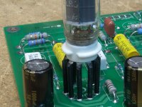
The SS diodes go in the PC board in the same location as the rectifier tube. They generate no heat and need no holes in the deck, so they are not visible from the top. See the picture in post #537.
This is a picture of one of my amps that used SS rectification. My main focus here was small size since I have very limited space. I put the two OPT's on the deck and used an Antek toroid for power which is hidden under the deck. The amp will still not be perfectly symmetrical since the driver tubes are offset to keep them away from the rectifier tube.
Attachments
JohnL
You can mount all components on the UNDERSIDE of the PCB except the tube sockets. I already showed you a picture of the diodes mounted on the PC board INSTEAD of the tube socket. I found a picture on the net and KLUGED a rouff example of how your amp could look. You would need to cut holes for the tubes in the top of the box and suspend the PC board from the underside of the top plate. EDCOR only sell BLUE painted bells for their transformers but they will sell you extra UNPAINTED bell, which you could paint any color you want.
You can mount all components on the UNDERSIDE of the PCB except the tube sockets. I already showed you a picture of the diodes mounted on the PC board INSTEAD of the tube socket. I found a picture on the net and KLUGED a rouff example of how your amp could look. You would need to cut holes for the tubes in the top of the box and suspend the PC board from the underside of the top plate. EDCOR only sell BLUE painted bells for their transformers but they will sell you extra UNPAINTED bell, which you could paint any color you want.
Attachments
schematic Simple PP
Dear George,
where can I find a schematic of this amp on your website?
Regards
pieroh
I don't claim to be artistic, but I do like things that are symmetrical. I am foremost an engineer and I design things for function first, then fit the form around them.
Of course the rectifier tube is always the odball since it is usually a different size than the other tubes. This is the case in most amplifiers. The logical place to put the rectifier is on the centerline of the PC board to preserve symmentry. From an engineering standpoint this is about the worse place to put it.
The rectifier and surrounding circuitry handles hundreds of volts of 50 or 60 Hz. It also passes high currents in short bursts. The rectifier must be kept as far as possible from the input circuitry to avoid hum. The traces to and from the rectifier must be carefully routed to create the PC board version of a single point ground (SSE and TSE) or a ground bus (SPP).
The only place to put the rectifier electrically that would satisfy the symmetry criteria would be in the center of the back edge of the PC board with two output tubes on each side. The circuitry supporting the rectifier tube must be kept in its own island of ground with only one ground connection to the rest of the PC board at the negative terminal of the output filter capacitor. Designing a PC board for a tube amplifier is actually a lot like making a point to point version. Fortunately it only has to be done right once. Every exact copy of the correct design will be the same and hum free.
Placing the rectifier in the center of the back of the board will make the board a lot wider. A wider board costs more to manufacture and triggers an oversize charge with some PC board vendors. It also makes it harder for the finished amplifier to be built with the golden ratio without making it rather large.
Up until recently the active screen size of all TV sets and most computer monitors was 4:3 which is 1.33:1, HDTV is 16:9 which is 1.77:1. It used to be common to put speakers on the sides of 4:3 monitirs to make them wider. Now the speakers are on the bottom edge to make them taller.
I have made stilts from brass tubing with heat shrink over it.
Dear George,
where can I find a schematic of this amp on your website?
Regards
pieroh
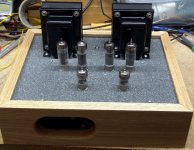
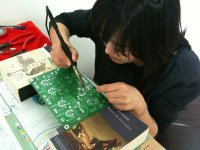
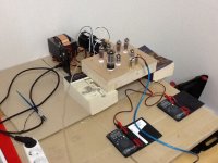
My valentines day present to the lady-friend arrived last week (SPP and parts kit). She got some time with the soldering iron in last weekend and managed to make it as far as the tube sockets (we couldn't resist mounting the tubes for fun... she was pleased).
With any luck, she'll make it over again in the next few days and we'll see if she can make it through the capacitors and terminal blocks (my K12-G crapped out and I have to use some crappy PC speakers until she finishes!). I expect the transformers to show up today.
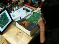
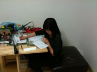
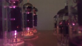
Since I'm not building this one, all I can do is watch Hitchcock movies and take photos... so that's precisely what I do.
With any luck, she'll make it over again in the next few days and we'll see if she can make it through the capacitors and terminal blocks (my K12-G crapped out and I have to use some crappy PC speakers until she finishes!). I expect the transformers to show up today.
Since I'm not building this one, all I can do is watch Hitchcock movies and take photos... so that's precisely what I do.
Attachments
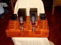
Everything fired up pretty well! B+ is just a breath under 310v. There's a steel case with a full enclosure for the transformers coming up next; it won't see much run-time in that wooden box.
I'll mess around with feedback and UL later on, for now it sounds pretty good. A touch of hum with my head near the speakers, but I'll chase that down later; for now we're smiling and the lady-friend is pleased as all getout.
I'll mess around with feedback and UL later on, for now it sounds pretty good. A touch of hum with my head near the speakers, but I'll chase that down later; for now we're smiling and the lady-friend is pleased as all getout.
Attachments
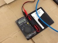
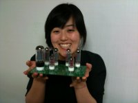
If you want any evidence of how disappointing the cameras on the ipad2 are, look no further than the above two photos. I have two far better cameras (a solid Canon point-and-shoot and a Canon DSLR), but as that line about "the best camera" goes, I use what's next to me. Sue took a few with her way-better camera phone...
Attachments
That's a great team effort! Good job. Those transformers look interesting, can you tell me what type they are and where you sourced them from?
Thanks, we had a pretty good time. We've both been spending too much time at work and pretty much only see each other on Saturday nights and Sundays, and a lot of that time is devoted to shopping/cleaning/laundry, so finding "stuff" to do together has been difficult.
The transformers are from a local shop here in Seoul DHTSound. Nothing fancy about them, just EI core jobs. Afer the OPTs arrived I wondered if couldnt have gone another size up. If you use the Chrome web browser and let it translate the page for you, it isn't too tough to navigate. The link to his transformers is the second from the top on the left menu. I've been to his shop once or twice and I think he winds them himself. He has a line of c-core OPTs that I might try for the TSE board I picked up with the SPP. He has a bunch of other misc. "boutique" audio parts too. I found a guy that makes his own line of cables not far off from him either. $20-$25 for his fanciest offerings in 1-1.5 meter lengths.
Finished my Tubelab SPP
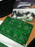
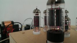
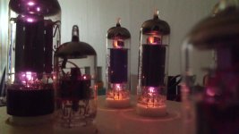
After 6 weeks, my Edcor transformers finally made it here, and I was able to finish my Simple PP build I started back in early Feb.
I only had two small issues. The first thing I noticed was that it would intermittently produce a loud scratching or popping noise, especially when the enclosure was tapped. I spent about an hour looking for a loose connection, until I noticed arcing in one of the EL84's. When I first received the tube, it had a bent pin. My guess is that me bending the pin back caused a very small air leak. That's the only thing I can think of. Or maybe it was just defective from the beginning.
So after replaced that set of tubes, it worked great! The only problem is that the 50k pot I purchased for a volume control is completely ineffective. I ended up having to install 1.4 M worth of resistors to temporarily get the volume to a reasonable listening level with both our turntable (w/ pre-amp), and our Mac. Is this normal? What POT values do others use? I'd like to have a POT that brings the volume down maybe 10% of the max volume. Suggestions...
The attenuation should be similar for any reasonable range of pot values (50k-500k). Did you get a logarithmic taper (otherwise known as an 'audio' pot)? Also, did you hook this up correctly? Do you get any reduction of volume, or only with the knob turned all the way down?
The pot forms a voltage divider, so the overall resistance value is only important to set the input impedance of the amp and the RC time constant with the Miller capacitance of the input stage.
The pot forms a voltage divider, so the overall resistance value is only important to set the input impedance of the amp and the RC time constant with the Miller capacitance of the input stage.
wiring UL Pentode switch
Hi All
Just coming to the end of my Simple PP Build")
So far everything has gone very well thanks to this well informed forum, many thanks to you all.
I'm having a bit of trouble working out how to wire a switch to select between UL and Pentode. I bought two DPDT on-on switches, one for CFB and the other for the UL/Pentode mode. A bit like this....

Ive been using the Simple SE wiring guide below, which works for most of the wiring, but its a bit different for the Simple PP.

Could someone confirm if i have the correct type of switch, and or offer any advice?
Many Thanks
Mike
Hi All
Just coming to the end of my Simple PP Build
So far everything has gone very well thanks to this well informed forum, many thanks to you all.
I'm having a bit of trouble working out how to wire a switch to select between UL and Pentode. I bought two DPDT on-on switches, one for CFB and the other for the UL/Pentode mode. A bit like this....
Ive been using the Simple SE wiring guide below, which works for most of the wiring, but its a bit different for the Simple PP.
Could someone confirm if i have the correct type of switch, and or offer any advice?
Many Thanks
Mike
OPT for Simple PP: 9k?
Dear all,
I am looking for output transformers for my SPP kit. Edcor is an option, but shipping from the US to Europe is rather expensive. Accordingly, I am looking for a vendor in Europe. "Ask Jan first" in Germany
http://www.die-wuestens.de/eindex.htm suggested their ATRA0427 OPT:
"High quality low price PP OPT for 10 W and 2* EL 84 or 6V6 etc. This transformer has been made according to an old Telefunken design redesigned to modern core materials.
Primary: 9kOhms Raa
Secondary 4-8 and 16 Ohms. Coresize: EI 78"
From what I have found on the web, the quality of this transformer is very good for the 34 EURO price tag. According to Jan, a "high" production volume makes it possible to sell the ATRA0427 for a decent price.
I am eager to try them with my SPP kit, but are they a good choice? George's recomendation is something like 6.5k - 8k primary impedance, will these 9k transformers serve well in the SPP?
- Home
- More Vendors...
- Tubelab
- Tubelab Simple P-P