So on PS trans it would probably be better to spend on higher mA rating as George mentioned would be a + on his site.
I found a thread in AK with a guy who builds DHT SE with low Watt tubes (Under 10W) & swears by the 28 lb Hammond 1642 SE 5K 75W rated OPT. Pretty pricey to try , but you probably get what you pay for.
Hammond Mfg. - "Classic" Single Ended Tube Output Transformers - (1627 - 1642 Series)
Randy
$300 times two will definitely get you started on a big bucks unit, won't it?
That's just a drop in the bucket if you start looking at the line of C-core SE lineup from Audio Note.
Audio Note Output Transformers, A,B,C
Audio Note Output Transformers, A,B,C
Your right it looks like Ag is part of the reason,along with the expensive cores.
Audio Note
There group B PP OPT's look interesting as affordable, but they don't believe in UL though so one is out of luck for that option. They explained the B series are 50% under rated too.
Audio Note
Audio Note
PDF'S @ partsconnexion have more info too!
Audio Note
There group B PP OPT's look interesting as affordable, but they don't believe in UL though so one is out of luck for that option. They explained the B series are 50% under rated too.
Audio Note
Audio Note
PDF'S @ partsconnexion have more info too!
Last edited:
I would think the 25W Edcor OPT's would be more than enough. 20Hz to 20kHz at 25W.
Regarding the 2 power trannies, 300V vs 285V, hmmm, interesting choice. Nearly 20V difference in B+. The 285V one might run the heaters on the high side, but that is an easy fix (if required). 20V too much on the B+ is not so easy to fix. I haven't used Edcor trannies so I have no idea of their ratings vs actual measurements in an amp.
Regarding the 2 power trannies, 300V vs 285V, hmmm, interesting choice. Nearly 20V difference in B+. The 285V one might run the heaters on the high side, but that is an easy fix (if required). 20V too much on the B+ is not so easy to fix. I haven't used Edcor trannies so I have no idea of their ratings vs actual measurements in an amp.
Doesn't George state that a rated transformer at 300V works fine, even though the makers have a tendency to make them slightly over that amount? I would have to go back and reread his expose on the project and tubes, but believe he found that any 6GQ5/EL84 tube could take it.
Some of the other associated tubes, now that would be a different story. But I intend to keep to the above tube. I'm still undecided.
Some of the other associated tubes, now that would be a different story. But I intend to keep to the above tube. I'm still undecided.
John L,
Go with the 300-0-300. Build it stock. Start with a 5U4. After power-up, measure voltage on the plates, if its too HI, change to a 5Y3 or some
other 5 volt tube. If its low add to 2 SS diodes to make a full bridge.
The power supply can be tweeked a bit.
At first, I thought of using tube rectification, but have now changed my mind. And I have changed my mind for one over-riding reason.
You all will have to pardon me, but I am a very artistically inclined person. I work in the interiour design field, and make high dollar items for interiour designers. My Mother thinks she and Dad wasted all that money sending me to private HS and the Citadel, not to mention my own expenses in attaining a masters degree in Physical Anthropology. And I am constantly bemoaning the fact that I never went to collage and earned a degree in geology. I am doing my utmost to get my grandson pointed in that direction. Hell, Eugene Shoemaker is my intellectual hero.
But that aside, I know full well the importance of that tiny concept of 'beauty' and the 'Golden Ratio'. Humans, even other animals, are genetically predisposed to favour the Golden Ration(1/1.6) The most beautiful people have a face that upholds that ratio. Its just in our genes to be attracted to this symmetry.
I have a HP monitor that is of the 16:10 aspect ratio(1/1.6), but now monitors are all made with the new HD wide screen 16:9 ratio, which is not the Golden Ratio. I love that monitor because it is pleasing to my sense of beauty. The monitor I am typing on now, is a newer one, and it uses the new HD standard. And normally I would hate it, because my sense of beauty notices this. But HP uses a ploy to ease the sense of beauty problem by making the bottom frame bar bigger than the top bar. This artificially makes the monitor look more pleasing, and it helps reassure my subconscious, and if I had one of those with thin framing, it would drive me crazy.
Well, there is a 'beauty' problem with this project. The tubes are not symmetrically aligned because the PCP is set up so the tube sockets are just not artistically aligned. The rectifier is also off in left field. From an aesthetic point, it makes the amplifier 'wrong' to the eye, and in need of being hidden from view. This is why so many console 'pulls' are rebuilt into more pleasing units.
Perhaps George will find a way to correct this in the future. And perhaps he did try it, but couldn't get the PCP to allow for it. I'm not sure, but I am thinking of finding a way to elevate the tube sockets from the board.
Doing this is straight forward: just drill the holes and run the connection from the board to the decking above.
But that presents some problems. And If I remember correctly George has tried to discourage this process, but I will have to reread the construction manual. The more that parts are separated from each other, the easier it is for magnetic fields to create hum and distortion. So in order to make the distance as little as possible, I could position the tube holes, but raising the board close enough to the deck would be tricky if I wanted to make the wire connections as close as possible.
I have to think this thing through more before making a decision, but I really want to have the finished product be something that people will want to admire.
And don't get me wrong, I chose this kit because it offers the best bang for the buck, is a proven winner, and has more than enough participants here, who can help get me out of any binds I may have. And I really expect to have a few, because I am new to making my own amplifiers.
I've just got to think of some way to be able to solder tube sockets on the decking, position the PCB properly, and then solder the connections to the board, doing it in such a manner that the distances are as short as possible. I think I have something in mind but haven't finalized it in my mind yet.
John L
What are you going to use, tube or SS diodes? It mades a big difference. If you use SS diodes alone, the B+ WILL be too high with a 300-0-300vac transformer. Tube rectifiers drop considerable voltage and that drop was anticipated in the design. If you use SS only, you will need to use a power transformer with a lower secondary voltage. Not having tested the amp with SS only, I cannot recomend a voltage value. Moving the rec tube is possible but opens up a can of worms...
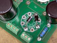
If you want to use SS diodes, leave the tube socket off and solder the diodes directly on the PCB without a socket and get a power transformer with a lower secondary voltage. George shows a picture of this configuration in the assembly manual.
What are you going to use, tube or SS diodes? It mades a big difference. If you use SS diodes alone, the B+ WILL be too high with a 300-0-300vac transformer. Tube rectifiers drop considerable voltage and that drop was anticipated in the design. If you use SS only, you will need to use a power transformer with a lower secondary voltage. Not having tested the amp with SS only, I cannot recomend a voltage value. Moving the rec tube is possible but opens up a can of worms...
If you want to use SS diodes, leave the tube socket off and solder the diodes directly on the PCB without a socket and get a power transformer with a lower secondary voltage. George shows a picture of this configuration in the assembly manual.
John L
What are you going to use, tube or SS diodes? It mades a big difference. If you use SS diodes alone, the B+ WILL be too high with a 300-0-300vac transformer. Tube rectifiers drop considerable voltage and that drop was anticipated in the design. If you use SS only, you will need to use a power transformer with a lower secondary voltage. Not having tested the amp with SS only, I cannot recomend a voltage value. Moving the rec tube is possible but opens up a can of worms...
If you want to use SS diodes, leave the tube socket off and solder the diodes directly on the PCB without a socket and get a power transformer with a lower secondary voltage. George shows a picture of this configuration in the assembly manual.
Oh. I'll have to think about this a bit more. Where can I put that tube so it looks like it really belongs?
Will there be any real problem with moving the tube sockets around a little bit? Also, I intend to construct transformer covers, which have steel sheet fit inside and soldered in place. That would naturally add magnetic shielding I believe.
Only you can answer that question.Where can I put that tube so it looks like it really belongs?
I think the amp looks just fine the way it is. Long wires with high AC current cause noise in the input section of the amp.
If you are going to relocate the rectifier tube, run the secondary B+ and heater wires to the socket instead of the PCB. Then you can put it where ever you like. If you are going SS, then you need to account for the missing tube drop (about 15-20V).
As far as relocating the other tubes, it should not be a problem provided you keep the leads between the sockets and PCB short and neat. The circuit is pretty stable.
As far as relocating the other tubes, it should not be a problem provided you keep the leads between the sockets and PCB short and neat. The circuit is pretty stable.
I would keep the 5AR4 for the slow ramp up of the B+ it gives, which George mentioned is very beneficial. You can put it where you want and add the diode mod with UF4007 or better (quieter) for longer rect. tube life. Todays rect. tubes aren't built to as high a quality so this helps take a lot of the load and still get the slow warm up of the 5AR4.
Actually you could probably skywire the output tubes too if you do it right as the Dynaco ST-70 and Mark III etc. did it successfully.
tube rectifier diode mod
Randy
Actually you could probably skywire the output tubes too if you do it right as the Dynaco ST-70 and Mark III etc. did it successfully.
tube rectifier diode mod
Randy
what is meant by 'skywire'?
I have done a search and all I get are Youtubes to some animation program, or a music group.
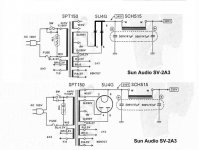
I notice that in George's and Ian's schematics, it calls for PT secondary connections to be to numbers '4' and '6'. I compared it to the rectifier diode mod, which shows the 5AR4 leads going to '5' and '7', and the diodes going to '4' and '6'.
Does this mean the original schematic had the 5U4 in mind?
I have done a search and all I get are Youtubes to some animation program, or a music group.
I notice that in George's and Ian's schematics, it calls for PT secondary connections to be to numbers '4' and '6'. I compared it to the rectifier diode mod, which shows the 5AR4 leads going to '5' and '7', and the diodes going to '4' and '6'.
Does this mean the original schematic had the 5U4 in mind?
I'm using George's term for mounting the output sockets remote from the board to use a different type of tube.
I believe 5AR4 is what George spec'd. The diodes are put on 5 & 7 as they are unused pins. This saves using a terminal strip.
The diodes have to be in series to the rect. tube as shown.
I believe 5AR4 is what George spec'd. The diodes are put on 5 & 7 as they are unused pins. This saves using a terminal strip.
The diodes have to be in series to the rect. tube as shown.
Last edited:
I'm using George's term for mounting the output sockets remote from the board to use a different type of tube.
I believe 5AR4 is what George spec'd. The diodes are put on 5 & 7 as they are unused pins. This saves using a terminal strip.
The diodes have to be in series to the rect. tube as shown.
I'll have to go back and reread that entire section again, just to familiarize myself with it.
This how to use SS diodes only.
I remember that picture, but didn't follow the point all that closely before. That's what happens when I am in too much of a hurry. Next time I'll make sure and process it.
I'm going to use the tube though, now that I can bypass the pcb. Setting it in front of, or next to, the power trans is where it should be placed anyway.
I think so anyway.
Last edited:
Pic of Dynaco St-70 with output and rect tube separate of PCB.
AudioKarma.org Home Audio Stereo Discussion Forums
AudioKarma.org Home Audio Stereo Discussion Forums
AudioKarma.org Home Audio Stereo Discussion Forums
AudioKarma.org Home Audio Stereo Discussion Forums
- Home
- More Vendors...
- Tubelab
- Tubelab Simple P-P