First, it's getting hard for me to remember your situation mixed in with other peoples posts. It's seems like you need some focused help. Please start a new thread and put all the details in the first post (what transformers, what tubes, your voltage measurements, etc).
398 - 366 = 32V
(32 ^ 2) / 150 = 6.8W <-- why R1 is so angry...it's a 5W part.
366V of B+ is too much. Set your meter to AC volts and measure the voltage between the two red wires, the two yellow wires, and the two brown wires. Are you located in the US? Does the power transformer get very hot?
There are ways to drop your B+, such as reducing the size of C1 to something like 10uF. BTW, what values are you using for C1 and C2?
OK, I found the post where you listed the tube types. If you are using JJ EL84s, then they are probably surviving the high B+ just fine. Other modern production types would have melted screens by now. Still, you should be seeing more like 300-325V with that power transformer. Something isn't right.
I'll do that when I get home tonight.366V of B+ is too much. Set your meter to AC volts and measure the voltage between the two red wires, the two yellow wires, and the two brown wires
I'm in chicago and the transformer didn't get very hot at all.Are you located in the US? Does the power transformer get very hot?
I'm doing exactly that to R6 in the TSE. R1 definitely needs to be uprated to a 7W part at least. My SPP will be getting a choke in place of R1, if I ever get around to it. ")
I mentioned the issue with R1 to George over email some time ago (last year?), but I know he has a hard time keeping up with all the emails. Mine is pretty toasted looking now (I use the SPP in my shop), but it's still alive.
I mentioned the issue with R1 to George over email some time ago (last year?), but I know he has a hard time keeping up with all the emails. Mine is pretty toasted looking now (I use the SPP in my shop), but it's still alive.
I'll do that when I get home tonight.
I'm in chicago and the transformer didn't get very hot at all.
OK...I just wanted to make sure you weren't on 240 or something.
George, Hello. I would like to buy the Simple P-P board and kit. I am ok if it is missing the 39 ohm 5 watt resistor in the 6CW5 version built without a power supply choke for $35 (board) + $65 (kit) in the $8 small flat rate box shipped to Atlanta (30115) for a total of $108. Please let me know how to proceed. Thank you, Buz 770-595-4440Sherri put together 10 parts kits for the Simple P-P last year when she was here. At the time I ordered enough parts for 25 kits and enough small parts for 100. It took most of last year to sell those 10 kits and there has been no requests for more until this week. I have recently received several requests for kits, so I counted the remaining parts (I robbed some to make my own amps) and made some more kits. The people who already emailed me will get first choice and then the rest are up for grabs.
I have put together 7 parts kits since they seem to have become rather popular in the last week. The only Item that I am short on is the 39 ohm resistor that is only used in the 6CW5 version built without a power supply choke. I have 2 of them and I will get more next time I order parts. So there are 2 kits with everything, and 5 more that don't have the 39 ohm 5 watt resistor. Someone expressed interest in building a 6CW5 version so the complete kits should go to that person.
All of the parts were purchased last year before the prices went up on electrolytic caps, so I will still sell them for $65 each (same price as last year). Boards are $35 each. I can put 1 board and 1 parts kit in the small flat rate box which I can ship inside the US for $8. Anything bigger than that requires the medium flat rate box which I can ship for $13.
The remnants of tropical storm Emily blew through here yeaterday afternoon with strong winds and rain today as well. My power and internet have been intermittent most of today, but seems OK now.
PM me or email if you are interested. If there is sufficient interest I can get more parts. There are only a few items missing.
I can no longer answer Tubelab email from work and I don't get home until late, so sometimes I may not answer until the next weekend.
Would you have any problem with the suggestion that R1 be increased to 10W dissipation, or finned aluminum case(Dale, etc) bolted to metal chassis with short flying leads? I've seen that done with cathode resistors on EL84 & 34s
When I concieved of the Simple P-P the plan was to design the board so that it would work with the stuff being sold on Ebay as "EL84" and even "7189" or "7189A". Most of these tubes will melt if operated on more than 325 volts or so. With 300 or 325 volts the resistor runs at a warm but livable 4 watts or so. Then I found the JJ EL84's and cranked up the juice. Now the resistor runs at a rather toasty 6 watts or so. I have never seen one of the white ceramic Xicon 5 watt resistors fail at 6 watts. In fact I have run them at 10 watts without the resistor failing, but the solder joints will become brittle over time. I did blow one, but it took an extreme overload that also fried the cathode bypass cap (SSE with 6DQ6's on 450 volts). Replacing the resistor with a larger wattage rating would be the safe thing to do.
Remember that there are two ways to make a resistor handle more power. One is to make it larger so that it has a larger surface area to radiate the heat. The other is to use higher temperature materials in manufacturing the resistor. This doesn't remove any more heat from the part, it just operates at a higher temperature. This is not a good choice in PC board applications or in other situations where there is restricted air flow. Chose a resistor that is physically larger over a smaller higher wattage part. Or just make sure the 5 watt part is in good thermal contact with the chassis. Apply some heat sink compound if needed.
then R1 legs melted right off.
Something is very wrong here. R1 does get hot, but there is no way the legs should melt off.
You can easily use SS diodes in place of the GZ34
You can use SS diodes in some applications. It is NOT advisable in this situation. Replacing the tube rectifier with diodes will INCREASE the B+ voltage.
It sounds like you might have a short somewhere past R1.
I don't think that there is a short. If the voltage readings are correct the current is a bit over 200 mA which is higher than normal, but not outrageous given the high B+ voltage. This alone might shorten tube life but will not cause weak and distorted sound. Something else is wrong.
To help the diagnosis two things would help:
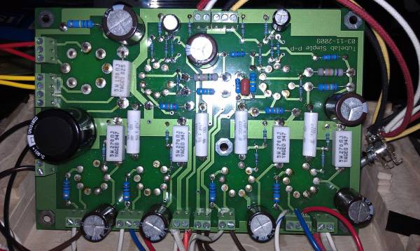
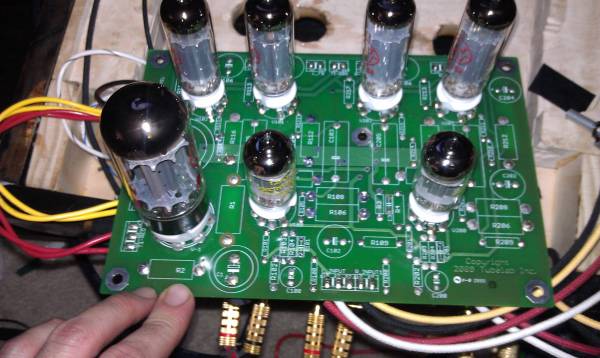
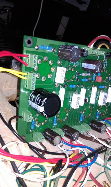
Post a good picture (or several) of your board so that we can see the resistor values and capacitor polarities. We also need to see the connections where the transformer wires connect to the PC board.
We need some accurate voltage readings. Here's how. Connect the black meter lead to ground. Set the meter to DC volts and a range above 400 volts. Most meters have a 600 or 1000 volt range. If you are comfortable probing a live board, turn the board on with no music applied and take readings on the following points and report the results. If not connect the meter to each point with a clip lead, turn the board on and wait for the reading to stabilize (about 1 minute) write down the number, shut the board off, wait at least 1 minute for the residual charge to dissipate and move the meter to the next point and repeat.
Get readings on the end of these resistors closest to the output tubes:
R212, R216, R112, R116. It should be about 12 volts.
Each end of R1, C203, C205, C103, C105, R209, R109, R208, R207, and R206.
Switch the meter to AC volts and probe the connection where the power transformer connects to the board at each of the T1-red points.
George, Hello. I would like to buy the Simple P-P board and kit.
Send the $108 to the email address shown on my web site Tubelab.com. I can't post the email address here because the spam bots will find it. Make sure that you mention SPP board and parts kit in the text or subject line, and make sure your address on file with Paypal is correct. The kits now have all the parts including the 39 ohm resistor.
sorry im a little late I just got home from work but here we goGet readings on the end of these resistors closest to the output tubes:
R212, R216, R112, R116. It should be about 12 volt
R116=11.7 R112=11.7
R216=12.1 R212=12.2
R1=339,368
C203=216,0 C205=106,0
C103=220,0 C105=104,0
R209=329,340 R109=328,340
R107=0,104 R207=0,107
R106=102,328 R206=104,328
R108=220,328 R208=217,328
T1-RED=637
I'll up load picture as soon as I can.
thank you very much
Nate
I'm doing exactly that to R6 in the TSE. R1 definitely needs to be uprated to a 7W part at least. My SPP will be getting a choke in place of R1, if I ever get around to it.
actually I did the same myself - IIRC it required breaking a foil trace on the board to
After identifying an early problem with defective rectifier tube that kept blowing mains fuses, the warmest running part on mine is the power transformer. I've been thinking about converting to SS diodes to relieve some of the thermal load on filament taps - that'd be a lot easier than upsizing the PTX. With existing choke and possible addition of film caps in the power supply, and maybe adjusting series R to keep B+ in line, I doubt I'd hear enough difference in the particular system.I mentioned the issue with R1 to George over email some time ago (last year?), but I know he has a hard time keeping up with all the emails. Mine is pretty toasted looking now (I use the SPP in my shop), but it's still alive.
LED's in the cathodes of the EL84's?
You could try these Fairchild MV50152.
http://i198.photobucket.com/albums/aa160/birdy81260/LEDarrays1.jpg
http://i198.photobucket.com/albums/aa160/birdy81260/LEDarrays3.jpg
You can get them from here.
Biasing can be tricky, and depends a lot on the B+ of the amp, the output tubes and the matching of the LED's.
The choke and motor run cap provide some benefit , even a littel , or are completely unnecessary ?
In this and several other projects (SE and P/P) appropriately spec'ed chokes and film caps in power supply were worth every penny. I've never heard anyone complain of sonics of motor run caps, but they certainly can impose some dimensional if not budgetary issues.
- Home
- More Vendors...
- Tubelab
- Tubelab Simple P-P