Hi @itsikhefez , Interesting, thanks!There are lots of posts asking about the gNFB feedback compensation cap.
I am building my third SPP, this time with Sowter OPTs (that seem to be of very high quality, BTW), and thought I'd share a FR graph of different cap values.
With this OPT, FR is pretty flat in the audio band, so I'm not even sure if a cap is necessary, but I experimented with 0pF-390pF.
With 0pF (no cap), the HF continues to rise and is likely truncated only due to my sound card sample rate?
With 390pF, the amp becomes unstable at max output power, so that is too high.
150-220pF seem to be the optimal capacitance, for this specific OPT.
I also have very good quality transformers - original Partridge 8K I was lucky enough to find second hand - and I am blown away by the sound difference. The only issue is that the sound gets very 'harsh' at higher volumes with the high frequency elements. I just fitted 470pF for the NFBK because I saw that was a suggested optimum value. I do realise I have to take the time to optimise the value. Unfortunately it is a bit fiddly to play with different values.
From your graph the 470pF should have suppressed a lot of the higher frequency elements more than a lower value capacitor, so if harshness is an issue then it is unlikely to be the feedback capacitor that is the sole solution?
I am thinking that it is worth having a Zobel network across the OPT, and then optimising the choice of feedback capacitor for the ringing on the square wave. Have you ever used a Zobel at all? If so what values did you use?
Cheers, Richard
I posted this in another thread, but wanted to share my new completed Tubelab SPP here also, in case it’s helpful to anyone undertaking a similar build. Two switchable inputs, feedback on/off switch, and two mode switches (one for each channel) to choose triode, pentode or ultra linear. Special thanks to Steve (Wall of Sound) for his great article! I also used a bias adjustment mod. Works perfectly!


Someone was asking about PCBs as Tubelab were no longer selling? Take a look on https://www.pcbway.com/project/shareproject/Tubelab_Simple_PP_amplifier_224059fa.html
Note, I have no affiliation to the site or the publisher.
Note, I have no affiliation to the site or the publisher.
That is NOT me and those are NOT my boards. Emails to PCBWay go unanswered. My designs are public domain. Anyone can build them and do what they want with them. My artwork (the PCB itself) is copyrighted, so making an exact copy of my boards is a violation of copyright law. This person did his own layout, so his board does not violate my copyright. Tubelab Incorporated IS a United States corporation and the unauthorized use of the Tubelab name with a possibly inferior product IS a violation of US trademark law. It seems that nobody in the Ukraine or China gives a flying fork about US trademark law.Someone was asking about PCBs as Tubelab were no longer selling? Take a look on https://www.pcbway.com/project/shareproject/Tubelab_Simple_PP_amplifier_224059fa.html
Note, I have no affiliation to the site or the publisher.
I have no idea if the person doing these layouts of other people's work knows what he is doing or not, but I would not support his actions by buying his stuff.
My wife and I are co owners of Tubelab. She has wanted it to be shut down for some time, but I have not. I reluctantly agreed to end operations last year, but when I posted that here people bought enough boards to pay off the Tubelab credit card, buy some more boards, and take a couple shots at possible new products. Sales have gone flat in 2024 so I don't know how far the Tubelab ride will take me, but this is year #19, far further than I expected in 2005 when I started.
@Tubelab_com As you say, it seems the guy has redone the layout using the schematic where he credits Tubelab.com next to his somewhat similar PCB layout....
I can't comment on Ukraine wrt copyright and it seems he is using the Tubelab name as an identifier rather than claiming the PCB to actually be a Tubelab_com product. As for China, we all they typically they have no regard for copyright and will copy anything and everything!
A fine line, but maybe a homage to your work? How would you rate his PCB design?
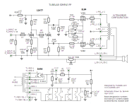
The schematic he is using was lifted from my web page. It was drawn by forum member Ian444 (noted on the schematic itself) after a stupid computer trick ate all of my original SPP files. I used it with his permission.
On my computer the images I can see of his layout do not have enough resolution to see the individual traces other than the heaters. This could be a poor picture, or a lousy board design. I know that I usually do several iterations of a layout, with a build and test of each, before I get something I'm happy with, but I do tend to be a perfectionist. I had issues with some poor quality copies of my SSE board being sold on Ebay several years ago, but Ebay quickly fixed that. Those boards would not have lived long due to the narrow runners with minimal spacing often seen in low voltage work.
On my computer the images I can see of his layout do not have enough resolution to see the individual traces other than the heaters. This could be a poor picture, or a lousy board design. I know that I usually do several iterations of a layout, with a build and test of each, before I get something I'm happy with, but I do tend to be a perfectionist. I had issues with some poor quality copies of my SSE board being sold on Ebay several years ago, but Ebay quickly fixed that. Those boards would not have lived long due to the narrow runners with minimal spacing often seen in low voltage work.
Yes, I saw the circuit diagram posted on PCBWay and noted that it was the same one as your website, and that you had commented about it being re-drawn by Ian444 and that you had posted it with his permission.
From what I understand, the PCBs offered are manufactured by PCBWay and the designer has to submit Gerber files rather than some dodgy photo of someone else's design. Designers are able to "share projects" such that third parties can order PCBs. "PCBWay Donate 10% cost To Author" (sic) from any PCBs manufactured.
If I can, I will private message you with some screen shots to help with any further action.
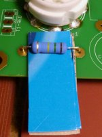
I like to solder resistors spaced off of the board a little bit. I use 2 or 3 layers of cereal box cardboard or similar to space the resistor. After soldering, I slide them out, see pic. Also, wherever possible, I solder components on both sides of the board. This is especially important with tube sockets as they undergo more stress and strain.
Attachments
My SPP is still running over 10 years later and I still love it. More thanks to George!Listening to one of my SPP amps as this is typed, with a Pass B-1 buffer. May be the best amps I own. Thanks George.
I ended up using a Triad VPT230-700 power transformer with a hand-wound heater winding using 23 turns 1.2mm enamelled copper wire and a bridge rectifier (rectifier tube no longer used). This tranny is super cheap with free shipping from Mouser and runs very cool, unlike the Antek it replaced.
Oh I see where you're heading with this, you want to use it with a SPP but keep the tube rectifier. You can do that just by feeding the rectifier DC. This protects the rectifier and also gives the turn-on delay. I've seen a few circuits do this. You would need to add a 2nd heater winding for rectifier tube.
- Home
- More Vendors...
- Tubelab
- Tubelab Simple P-P