Hi All,
I am in the process of ordering parts for a simpe SE build. I am using Edcor CXSE25-8-5K OPT and I have a few questions.
1. With this OPT, can I add a Triode/UL switch? Should it just be a single pole and what amperage?
2. Is it recommended to add the Cathode feed back switch? Single pole and what amperage?
3. Adding a motor run cap, does this replace C2 or is it place in paralle with it? Are motor run cap electrolitic?
thanks,
skipper
1. With this OPT, can I add a Triode/UL switch? Should it just be a single pole and what amperage?
yes you can, use a DPDT(on-on) switch. Just about any switch you find should work. I think mine are rated for 250volts and 6amps. I got it off of mouser. You could also check with apexjr.com I think they have some in which should save you a couple of bucks.
2. Is it recommended to add the Cathode feed back switch? Single pole and what amperage?
I would add it also, use a DPDT(on-on) switch. Just about any switch you find should work. I think mine are rated for 250volts and 6amps. I got it off of mouser.
3. Adding a motor run cap, does this replace C2 or is it place in paralle with it? Are motor run cap electrolitic?
It doesn't replace it. Motor run capacitors I believe are mainly if not all Polypropylene Film in oil. I got mine off of ebay.
Paul answered your Q's, but just to add:
1-2) As he said, pretty much any DPDT switch will work. The switches won't see more than 100 milliamps or so. The UL/Triode switch does deal with a lot of voltage, though...more than any "normal" switch is rated for. We are all probably using 250VAC switches, but most switches can handle much higher voltages as long as the current is sufficiently derated (which it is in our case). The only reason I bring it up is because I recommend that you get a switch whose body can be grounded to the chassis. If for whatever reason the switch body insulation breaks down under the high voltage, the worse that is likely to happen is a blown fuse. Getting zapped by 400V is much worse. Any metal toggle switch should do the job just fine.
3) George has a pair of terminals for the motor run cap. You still put the on-board 'lytic in there, regardless.
I have a Radio Shack 2 pole 6 position rotary switch for switching between UL/Triode/Pentode on my dual mono KT88 SE build.
This one:
http://www.radioshack.com/product/index.jsp?productId=2062536
Just don't switch modes with power on
This one:
http://www.radioshack.com/product/index.jsp?productId=2062536
Just don't switch modes with power on
rknize said:3) George has a pair of terminals for the motor run cap. You still put the on-board 'lytic in there, regardless.
What makes you say that? Mine's been running fine for months without a single electrolyic installed at either C1 or C2.
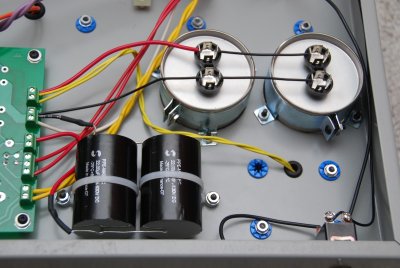
And George looked at the pictures and thought it looked great.
LOL...I'm not implying that you *can't* use all foil caps in the PSU! The design of the board is such that the intent is to use the on-board lytics using the supplied parts list. He provides extra terminals that allows a simple way to bypass that cap with a film one. You are certainly free to do whatever you please!
The design of the board is such that the intent is to use the on-board lytics using the supplied parts list. He provides extra terminals that allows a simple way to bypass that cap with a film one.
Neat idea. I always assumed the "auxiliary cap" connection was to add a big (80uF to 120uF) motor run cap to the power supply. I never considered using it to add a small film cap, bypassing C2 (the 120uF electrolytic cap installed on the board). Has anyone tried using it this way? What were the results? I've got some extra Orange Drop 630V rated caps. They're small, maybe 0.01 uF? I wonder if adding one would be useful...
From a point of view of current paths, I suspect it would be best to bi-wire the off-board capacitor (i.e. one pair of wires coming from the rectifier/choke, and another pair going to the load. For the same reason, putting the best quality (lowest ESR) cap in the position closest to the load.
Though at valve impedances, it may not matter that much.
Though at valve impedances, it may not matter that much.
- Status
- This old topic is closed. If you want to reopen this topic, contact a moderator using the "Report Post" button.
- Home
- More Vendors...
- Tubelab
- simple SE questions