A little backstory...I've been listening to music through tube amps for most of my life. One in particular. They are all push-pull. I'd rather listen to my medium-fi Thomas amp than most of the SS gear I have tried over the years. After listening to my friend's nice SE gear as well as some stuff at one of those snobby audiophile type stores, I figured i'd give SE a try.
So my plan to enter the land of single endedness was to build something that wasn't too complicated and preferably used tubes that I already had. That is what attracted me to the Tubelab Simple SE. When I ordered the PCB, I had also picked-up a couple of George's original SE boards. One I figured I'd build-up sometime later and the other was for experiments. I ordered some other iron from AES and decided to spring for the UBT-2s at the time as well. Well both PCBs are built and I've been getting impatient waiting for my Edcors to show up.
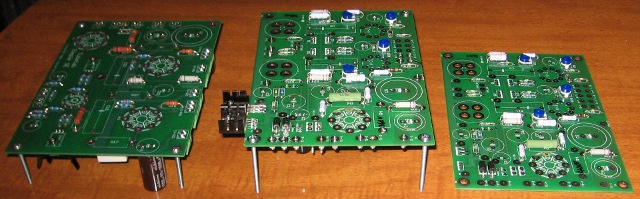
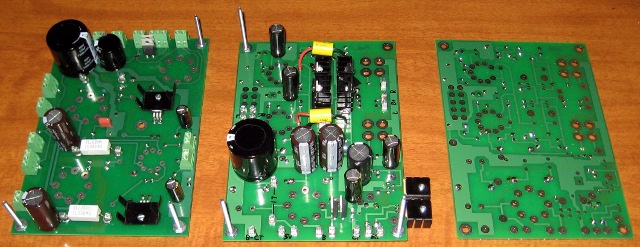
I scrounged around and found a 700VCT transformer that would work in the Tubelab SE if I omitted C4. I had some 5842s and so I shopped eBay and won a couple of random used 45s. And so, even though I never thought 2W would ever be enough to really satisfy me, here I am listening to this thing all cobbled-together. The only snafu I ran into was I didn't read the directions carefully and installed the 4-pin sockets backwards (following the silkscreen). Luckily I only bent one tab on each pin, so I was able to reuse the sockets with no problems.
I don't own any speakers that should be used with an amp like this. The "best" ones are a pair of Boston Acoustic A60s. They are pretty much original except that I refoamed the woofers. I have to say that I was quite impressed with the amount of bass I was hearing, but the SE was definitely huffing and puffing a bit to get these things loud. I noticed a bit more "detail", but not that much. I haven't touched the crossovers on these speakers yet. I decided to connect my pair of old Ratshack Realistic Nova-18s, since I know they are more efficient. These are not the best speakers by any means, but they actually don't sound too bad, especially after I put a Solen Fastcap in place of the lytic on the tweeter. They are lacking in the midrange, but the bass is extended if a bit floppy at times. I put some random track on and I was totally floored. I have never heard these speakers image like this before. I started playing all kinds of music and was up until 4am listening to this thing. The volume level was much better, the bass was powerful, and the detail was more than I have ever heard these cheap speakers do.
Now I really want to know what 8W from the SimpleSE will be like....
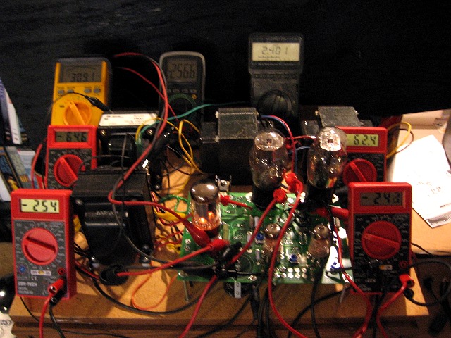
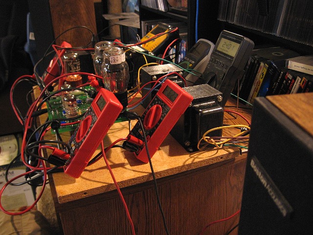
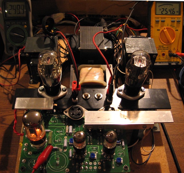
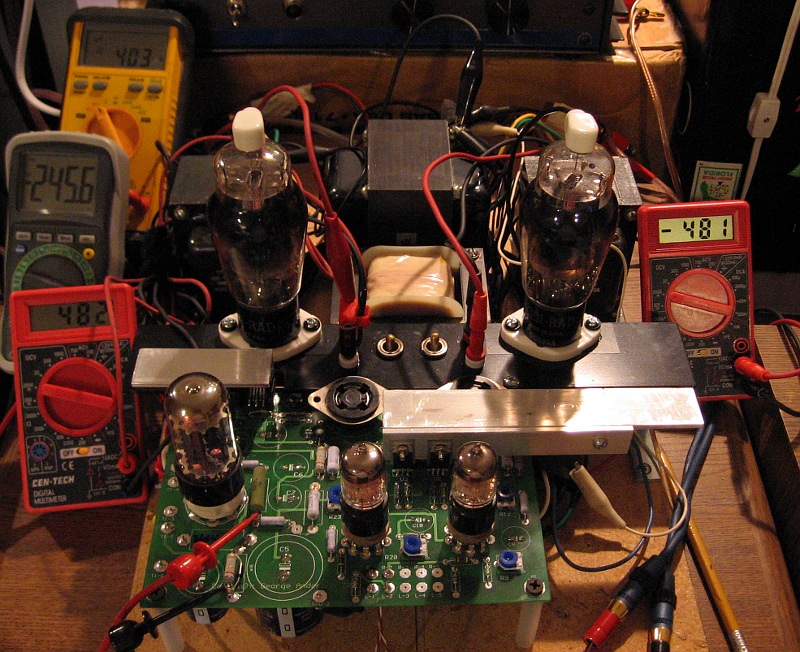
ANYWAY...I do have some technical questions...seriously. If you notice from the pictures, I built the boards for chassis mounting. The heater regulators are sticking off the end and will be mounted to the chassis. However, I used the "stock" heatsinks for the CCSs and FETs since it looked like George got away with it in his Lexan amp. However when checking the temp of the sinks, I measured around 65^C on the CCSs and 98^C on the FETs. This is well beyond what I would typically let silicon run at. Is this typical? I guess I will have to fashion a bracket that will thermally connect these guys to the chassis as well. I know they are missing-out on convection, but I didn't think the FETs were pushed that hard. I'm using a 30k bias resistor on the source.
Also, R6 is quite toasty (around 150-160^C). I calculated over 5W being dissipated here. I'm using a 7W part, but it will need to be de-rated some once it is shrouded. I plan on venting the top of the chassis, but it won't be anything like an open board. Anyone have issues with this guy?
The 45 heaters are only getting about 2.4 volts. Should I tweak the reg to get that last tenth or is it fine? It's DHT, so I dunno if it matters any.
Going back to listen some more....
So my plan to enter the land of single endedness was to build something that wasn't too complicated and preferably used tubes that I already had. That is what attracted me to the Tubelab Simple SE. When I ordered the PCB, I had also picked-up a couple of George's original SE boards. One I figured I'd build-up sometime later and the other was for experiments. I ordered some other iron from AES and decided to spring for the UBT-2s at the time as well. Well both PCBs are built and I've been getting impatient waiting for my Edcors to show up.
I scrounged around and found a 700VCT transformer that would work in the Tubelab SE if I omitted C4. I had some 5842s and so I shopped eBay and won a couple of random used 45s. And so, even though I never thought 2W would ever be enough to really satisfy me, here I am listening to this thing all cobbled-together. The only snafu I ran into was I didn't read the directions carefully and installed the 4-pin sockets backwards (following the silkscreen). Luckily I only bent one tab on each pin, so I was able to reuse the sockets with no problems.
I don't own any speakers that should be used with an amp like this. The "best" ones are a pair of Boston Acoustic A60s. They are pretty much original except that I refoamed the woofers. I have to say that I was quite impressed with the amount of bass I was hearing, but the SE was definitely huffing and puffing a bit to get these things loud. I noticed a bit more "detail", but not that much. I haven't touched the crossovers on these speakers yet. I decided to connect my pair of old Ratshack Realistic Nova-18s, since I know they are more efficient. These are not the best speakers by any means, but they actually don't sound too bad, especially after I put a Solen Fastcap in place of the lytic on the tweeter. They are lacking in the midrange, but the bass is extended if a bit floppy at times. I put some random track on and I was totally floored. I have never heard these speakers image like this before. I started playing all kinds of music and was up until 4am listening to this thing. The volume level was much better, the bass was powerful, and the detail was more than I have ever heard these cheap speakers do.
Now I really want to know what 8W from the SimpleSE will be like....
ANYWAY...I do have some technical questions...seriously. If you notice from the pictures, I built the boards for chassis mounting. The heater regulators are sticking off the end and will be mounted to the chassis. However, I used the "stock" heatsinks for the CCSs and FETs since it looked like George got away with it in his Lexan amp. However when checking the temp of the sinks, I measured around 65^C on the CCSs and 98^C on the FETs. This is well beyond what I would typically let silicon run at. Is this typical? I guess I will have to fashion a bracket that will thermally connect these guys to the chassis as well. I know they are missing-out on convection, but I didn't think the FETs were pushed that hard. I'm using a 30k bias resistor on the source.
Also, R6 is quite toasty (around 150-160^C). I calculated over 5W being dissipated here. I'm using a 7W part, but it will need to be de-rated some once it is shrouded. I plan on venting the top of the chassis, but it won't be anything like an open board. Anyone have issues with this guy?
The 45 heaters are only getting about 2.4 volts. Should I tweak the reg to get that last tenth or is it fine? It's DHT, so I dunno if it matters any.
Going back to listen some more....
I built my Tubelab SE with 300B so my info may not be much of use for you however, I would mount an additional heat sink to U1 the way Tubelab did. Put a few small holes at the top and bottom of chassis where this new heat sink will be located. As they say, heat is one of the biggest enemies in this hobby.
Thanks, Even. I do have U1 dangling off the end of the board so that I can mount it to the chassis, so I am not worried about that. It's Q1 and Q2 running over 95^C that has me concerned. It's getting close to what would be "spit sizzling" hot. I should be able to fashion some kind of bracket to pull the heat away and into the chassis, but it will just be another thing in the way.
I kept forgetting to measure the voltage across the 30k bias resistor to see where the FET was operating. So you don't notice the FETs getting disturbingly hot on yours? Is it top or bottom mounted?
Thanks,
Russ
I kept forgetting to measure the voltage across the 30k bias resistor to see where the FET was operating. So you don't notice the FETs getting disturbingly hot on yours? Is it top or bottom mounted?
Thanks,
Russ
The FETs have always run hot. I don't have a way to measure the temp, but is "cant touch lhis" kind of hot. Even at this temp, the Toshiba parts have been reliable. Parts from other vendors sometimes fail. I often add suplemental heat sinking, or reduce the current.
Some creative under chassis mounting arangements have been posted, including tube socket extensions. This was the path that I was going down before my amp building got put on hold last year.
Some creative under chassis mounting arangements have been posted, including tube socket extensions. This was the path that I was going down before my amp building got put on hold last year.
Thanks, George. I thought about extending the tube sockets, but after reading your concerns about the 5842's tendency to oscillate, I decided against it. I didn't want to increase the distance from the grid stopper, even though I went for the carbon comp in that spot. I suppose I could have tucked the stopper into the extended leg, but that would have been a bit precarious.
Do you have any thoughts about the filament voltage? I suspect it doesn't matter, but I thought I'd bring it up. Other than that, the board worked great and I was really impressed with what i could do with 2 watts. I imagine the transformers had a lot to do with it. After going back to the Dynaco and keeping the same speakers config, I'm not really sure what my ears were hearing because the imaging is still good. I now notice more punch in places, so I was probably pushing it too hard. I just need to spend more time with it.
As an aside, running with an LC filter as I did instead of a CLC did expose a lot of switching noise. I didn't put any snubbers on the (Hammond) choke and the stupid thing buzzed angrily. It was just temporary, so I didn't really care. Hopefully the choke won't buzz so much in a pi filter.
Russ
So after breadboarding the Simple SE and testing it out for a few days, I dismantled it and rebuilt the Tubelab SE on it. I finally found some good speakers for a good price (KLF-10s for $150). These speakers are fairly sensitive (98dB), much better than the A60s. Amazing bass, too. The horns really give me ear fatigue at even moderate volumes with the Dynaco, but with the Simple SE it was better. So I rebuilt this thing hoping it would be better still. It is. Must be the harmonics...I dunno. Something about it my ears like and yet the detail is amazing.
I think I'm going to build the chassis for this amp first instead of the Simple SE. All I need is a power transformer. I'm thinking of making a bit more universal than most by using a custom Edcor with some taps on the HT winding (thread here). I'm probably going to go "old school" with the chassis with a SS plate on a wood frame with as much iron tucked underneath as possible.
I think I'm going to build the chassis for this amp first instead of the Simple SE. All I need is a power transformer. I'm thinking of making a bit more universal than most by using a custom Edcor with some taps on the HT winding (thread here). I'm probably going to go "old school" with the chassis with a SS plate on a wood frame with as much iron tucked underneath as possible.
Specs for the custom transformer are posted here. I should have it in 3 weeks.
http://www.diyaudio.com/forums/showthread.php?postid=1783762#post1783762
http://www.diyaudio.com/forums/showthread.php?postid=1783762#post1783762
I've slowly been making progress on the chassis for this amp. I've re-breadboarded the amp to check out the final arrangement and see how the switchable B+ and heater voltage works. Oh man, I've missed this amp. With 45s in there...it has some kind of magic... Was listening to some old Erich Kunzel stuff...it was a hoot.
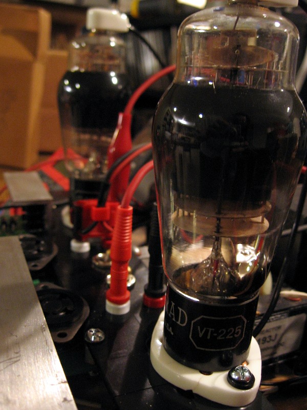
Here we are sporting the 5-pin sockets with a pair of VT-225s strapped as triodes. They sound quite nice. More grunt, like a 300B...not sure if they are as detailed as a 45 though. Need to spend some time with them. I'm running them at 50mA, which seemed reasonable. Any suggestions on bias current?
One of the tricks of this amp build will be modular sockets on the output tubes. The Tubelab SE can drive all sorts of things. The UBT-2s don't have UL taps, so I'll just stick with triodes and triode-strapped pentodes. I plan to make 2 or more different octal sets for driving EL34s and friends as well as sweep tubes. The 4 and 5 pin are these "johnson" style sockets, but the octals will probably just be the normal ones on little adapter plates.
This one's for you, George!
rknize said:...a pair of VT-225s strapped as triodes. They sound quite nice. More grunt, like a 300B...not sure if they are as detailed as a 45 though. Need to spend some time with them.
Nope...45s FTW. I was, or rather wasn't, noticing some things in some live recordings. Similar to the 300Bs, the VT-225s sound what I would call "veiled" compared to the 45s that are just so clean sounding. It wasn't until I was listening to some old, live Simon and Garfunkel recordings that I was finally convinced. They are not the best recordings but they just sounded so flat...I thought maybe I was playing the wrong album. It motivated me to go back to the 4-pin sockets. Sure enough...the 45s brought it back.
I'm starting to wonder if it maybe has more to do with the higher operating voltages when running 300Bs and VT-225s. Perhaps some interaction between the coupling cap and the gate capacitance of the MOSFET?
- Status
- This old topic is closed. If you want to reopen this topic, contact a moderator using the "Report Post" button.
- Home
- More Vendors...
- Tubelab
- (YATSE) Yet Another Tubelab SE (sorry...long)