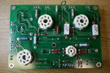
I took a bit of time today to so some work on my 1 yr old Simple SE that I had been meaning to do. I figured I'd share my results in case anyone is interested.
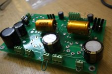
The two 1500uf 50v caps were a bit too tall for my chassis so I had cut two holes in the bottom of the chassis for them to poke out from. I decided I'd rather that they didn't do that so I replaced them with a pair of Nichicon KG's of similar value (LKG1H152MESBBK). The lead spacing wasn't quite right, but I bent them to fit. They're also a bit too wide so I had to relocate the cathode bias resistors to the other side of the PCB. In any case I'm happy with the result.
Anyone ever heard of the KG's before? I've gotten KZ's and ES's, and know about FG's, but KG's? Is this a new line from Nichicon?
Anyway since I had to move the cathode bias resistors I figured I'd change the values from 560 to 430 ohms for my Philips/ECG 6BG6GA's since they're supposed to be able to dissipate 35w on the plates. 430 should push 'em good and also work well with KT88's if I ever get a pair.
Attachments
I also replaced the dead FREDS that I snapped out after they shorted.
So how's it going? Well nothing exploded!") We'll actually my 6679 started to get crackly popish, so I replaced it. That's the 3rd 12AT7ish tube that I've gone through since I sparked the Simple SE up 12 months ago. I should check the heater voltage. The 6679's should be able to handle a bit of over voltage though.
We'll actually my 6679 started to get crackly popish, so I replaced it. That's the 3rd 12AT7ish tube that I've gone through since I sparked the Simple SE up 12 months ago. I should check the heater voltage. The 6679's should be able to handle a bit of over voltage though.
In any case the 6BG6's have been in for about an hour with no red spots. None. They're happy as can be. I'm also running off the hexafreds which I would expect to put the voltage a wee bit over 450v for the B+.
Before I wrap up here, has anyone measured the voltages on the 12AT7? I'm just curious how hard they're being pushed.
So how's it going? Well nothing exploded!
We'll actually my 6679 started to get crackly popish, so I replaced it. That's the 3rd 12AT7ish tube that I've gone through since I sparked the Simple SE up 12 months ago. I should check the heater voltage. The 6679's should be able to handle a bit of over voltage though.In any case the 6BG6's have been in for about an hour with no red spots. None. They're happy as can be. I'm also running off the hexafreds which I would expect to put the voltage a wee bit over 450v for the B+.
Before I wrap up here, has anyone measured the voltages on the 12AT7? I'm just curious how hard they're being pushed.
Attachments
whitelabrat said:Before I wrap up here, has anyone measured the voltages on the 12AT7? I'm just curious how hard they're being pushed.
Pretty hard, I think. I haven't actually measured mine but I did build a model in LTspice. It thinks the plate voltage is going to be around 250VDC at idle. Running 10 mA (assuming the CCS is doing its job) will give a 2.5 watt dissipation per side. That's right at the rated limit for a 12AT7.
whitelabrat said:Would one suppose that I could bring some stress off the 12AT7 by upping the value of R10 and R20?
I don't think so. It's the CCS that's running the show in this case. It'll just raise the plate voltage higher trying to maintain the 10 mA as best it can. For what it's worth, I seem to recall that George once mentioned somewhere the CCS used isn't particularly exact, and the 10 mA is really an approximate value. I think the actual current is slightly less.
I believe the correct way to adjust the idle current is by manipulating R19 and R29. I'm not sure which direction they need to go. I'm sure you could figure it out by consulting the data sheets for the IXCP10M45S. As you reduce the current, there will necessarily be a larger voltage drop across the CCS. I'm assuming the power dissipated in the CCS will remain the same (voltage drop is going up, but current is going down). If not, you may also need to adjust R14 and R24 to compensate.
Also keep in mind that reducing the idle current will result in a lower plate voltage on the 12AT7, and a smaller potential voltage swing coming out of it. I suspect you'll still have plenty of swing to fully drive the finals, but a full analysis is probably in order.
Ty_Bower said:I haven't actually measured mine but I did build a model in LTspice. It thinks the plate voltage is going to be around 250VDC at idle. Running 10 mA (assuming the CCS is doing its job) will give a 2.5 watt dissipation per side.
I started questioning where I got my own information. The 10 mA figure came from memory. I confirmed that I read the number here, on George's website.
The 250 volts came out of my LTspice simulation. Perhaps it has a crummy model for the 12AT7, or it just doesn't model realistically under the conditions presented by the CCS. Regardless, George's page (see above) indicates the plate is running close to 188 volts. That means the idle dissipation is quite a bit lower than I originally thought. I'd probably stop worrying about it at this point.
Yep, that's the only way to do it unless you do point-to-point. It adds a good 1.5 inches to the height of the tube, so I can't put the cage on top any more. Some day I'll scratch up something for KT88's. The 6BG6's are so cheap and I like they way they sound so that probably won't happen anytime soon.
OK, here is the deal. There are two things that contribute to the power dissipated in the 12AT7. As most know these are the voltage across the tube, and the current through it.
The current is forced by the CCS IC and that value is set by R13 and R23. The target current is 8 to 10 ma, which is generally obtained with a 330 ohm resistor. To lower the current raise the resistor value. Most of the 12AT7's that I have tried worked the best with currents from 5 to 10 mA. R19 and R29 are 1K ohm gate stopper resistors to prevent oscillation in the 10M45 chip.
The voltage across the 12AT7 is determined by its bias voltage since the current is fixed by the CCS chip. In this case the cathode resistor R10 and R20 will adjust the plate voltage. Lowering the resistor will reduce the plate voltage. I found that best results were obtained with a plate voltage of 175 to 200 volts.
R14 and R24 are there to reduce the dissipation in the CCS chips and shouldn't need adjusting. The only exception is when the board is used on low supply voltages (below 325 volts) to run tubes like 6V6, 6K6, 6Y6, or 6W6. In this case these resistors should be replaced with a wire jumper.
Simple SE driver tube thread
OK, so armed with some of the helpful information that George clarified above, I took a few measurements on my Simple SE. I also finally got around to trying out one of the odd "12AZ7N" tubes that I've got around.

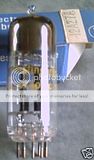
The 12AZ7 has (or at least, is supposed to have) virtually identical electrical characteristics as compared to the 12AT7. The differences are in a more voracious appetite for filament current, a much sturdier tolerance for H-K voltage, and subtle variations in the inter-electrode capacitances. Well, my 12AZ7N doesn't seem to behave much like a 12AT7 at all. My first clue was when I popped it into the emissions tester and it immediately pegged the meter. By my guess, it tests out to over 240% the emission of a real 12AT7.
First, I started with a Telefunken ECC81 in my Simple SE. I measured plate voltages of 215/224 and cathode voltages of 1.88/1.89. The cathode voltage can be used to calculate the idle current - ~8.5 mA. This agrees with the ~85 volt drop across R14/R24. The CCS is dropping the voltage from 400 volts down to the 220 volts seen at the plate, for a total of 1.5 watts dissipated in the CCS.
Next, I stuck my 12AZ7N into the driver socket. Cathode voltages remain identical, indicating the idle current is the same and the CCS is doing its job. The plate voltages are quite a bit lower - measured at 142/157 volts each side. I calculate each CCS is dissipating 2.2 watts in this case.
The informal listening test will be conducted shortly. Does anyone have any comments regarding these particular tubes, the lower than normal plate voltages, or the power handling capabilities of the CCS?
Does anyone have any comments regarding these particular tubes, the lower than normal plate voltages, or the power handling capabilities of the CCS?
The lower plate voltage is likely due to the different characteristics of these tubes. It can be adjusted by changing the value of the cathode resistor. If it sounds OK this is probably unnecessary. The CCS chip is rated for 35 watts on an infinite heat sink. That little heat sink is good for around 2 watts. Run the amp for a while, unplug it, then touch the heat sink. If bad language ensues it is too hot. The cure is a bigger heat sink, or a higher value for R14/R24. My guess is that it will be OK. I have a trimmer pot for the cathode resistor in my test amp so that I can plug in just about any tube.
I checked when you posted about this tube and I don't have any 12AZ7, and my favorite tube seller doasn't either. I have been sorting tubes for the past 6 weekends. I have gone through at least 15,000 tubes, finding all sorts of 9 pin dual triodes, no 12AZ7! I will be gone next weekend, but when I return I have a big bunch of tubes to "test".
tubelab.com said:I checked when you posted about this tube and I don't have any 12AZ7, and my favorite tube seller doesn't either. I have been sorting tubes for the past 6 weekends. I have gone through at least 15,000 tubes, finding all sorts of 9 pin dual triodes, no 12AZ7! I will be gone next weekend, but when I return I have a big bunch of tubes to "test".
Say the word and I'll send you one of these 12AZ7N. I've got a bunch of them. No need to send it back, either. Just let me/us know if you learn anything about it.
A quick update to this thread, although perhaps a bit off topic:
One note about the 6679s, and just about all my other 12AT7s is that they were all ebay iffy cheapos. Thats why they didn't last very long. Can't trust those ebay guys. In any case I recently got two sleeves of untouched 6679s and everything is doing great.
I finally got around to plunking in a pair of EH KT88's. These are really nice especially with the big OPTs. I can't wait to get my 15in Tannoy HPD's repaired.
One thing about the KT88's is that the Hammond 274BX really started buzzing (mechanically) like mad. I couldn't take it anymore so I ripped out the 274BX and plopped in a 373BX that I pulled off another amp. No buzzing. The only downside is the B+ dropped from 450v to 400v as expected. The 430ohm cathode bias resistor is too much for the job so I paralleled a 1.5k resistor on the other side of the board to get a total of 330ohms. Looking good.
I also stuck in a 0.1uF orange drop along with the 80uF film cap to help smush some of the solid state rectifier switching noise. I don't think it made a difference, but it's not noticeable when music is playing.
Looking forward to some of Tubelab's new boards. Pssst, one vote for a 6aq5 Simple P-P.
whitelabrat said:One thing about the KT88's is that the Hammond 274BX really started buzzing (mechanically) like mad. I couldn't take it anymore so I ripped out the 274BX and plopped in a 373BX that I pulled off another amp. No buzzing. The only downside is the B+ dropped from 450v to 400v as expected.
I didn't have any previous experience with the Hammond power transformers, but I ended up buying the 374BX for mine based on collected reports that the 300 series were mechanically more stable than the 200 series. I haven't been disappointed with my 374BX. It's 99.999% buzz and hum free. You can almost feel a slight humming if you place your fingers on it, but there's nothing audible.
With regards to the 373BX, I'd figure a 400 volt B+ would be a good thing if you intended to run mostly EL34 and 6L6 type tubes. Keep your output transformers closer to 3K (rather than 5K, which probably suits the higher B+ better) and you should be golden.
6BG6GA Lifespan
I am curious to hear how long your tubes last in the Simple SE. I bought a quad (6GB6GA)a couple years back with hopes of buying a cache of them because they were so cheap. About the time the seller raised his price $2 a tube two of the four tubes er ... a ... stopped transconducting. Anybody else have this trouble? These are the only power tubes I've had give up the ghost in over five years of "casual" listening. Maybe just my bad luck?
I am curious to hear how long your tubes last in the Simple SE. I bought a quad (6GB6GA)a couple years back with hopes of buying a cache of them because they were so cheap. About the time the seller raised his price $2 a tube two of the four tubes er ... a ... stopped transconducting. Anybody else have this trouble? These are the only power tubes I've had give up the ghost in over five years of "casual" listening. Maybe just my bad luck?
I assume you mean the Phillips-ECG 6GB6GA's? I've had a pair in mine for not much more than half a year, so I can't vouch for their lifespan. I'm guessing I was pushing them at about 66ma and then later 79ma at about 450v without any fuss which I find impressive. I don't get a lot of listening time either, maybe a couple of hours of time on the weekend so I'm not really putting a lot of time on them.
I've since switched to EH KT88's, but I'll likely go back to the 6GB6GA's once the KT88's give up.
I did try some old 6GB6G's. They turned red within about a minute or so, and I wouldn't expect those to last very long without tuning things down quite a lot.
I've since switched to EH KT88's, but I'll likely go back to the 6GB6GA's once the KT88's give up.
I did try some old 6GB6G's. They turned red within about a minute or so, and I wouldn't expect those to last very long without tuning things down quite a lot.
- Status
- This old topic is closed. If you want to reopen this topic, contact a moderator using the "Report Post" button.
- Home
- More Vendors...
- Tubelab
- Simple SE and 6BG6GA's