Thanks. New Sensor's reissued "Genalex" KT88 is a fine tube, albeit a touch expensive. I picked up a quad a while back for a Mk3 project I never finished. They had never been used (no place for me to plug them in), but I figured I'd give them a try in the Simple SE. I was pleased to see how closely they biased. Both came up pretty much at 40 volts across the 560 ohm cathode resistor, or about 71 mA each. I was also happy to see how closely it matched the old datasheets for the KT88. I had read reports these reissues tended to run hotter than expected, but that wasn't so in my case.
They don't have even ten hours on them yet. I don't know whether or not I buy into the whole "tube break-in time" theory. I will say they have a BIG bottom end. I don't know how else to describe it. The EH fat bottle 6CA7 that were in there before sounded full and balanced, but these KT88 are really all about solid bass reproduction. I wasn't expecting such a noticeable difference from a swap in power tubes. I figured the driver had more effect on the overall character of the amp.
Compared to the 6CA7, they do require just a hair more drive to get the same volume level. That suits me fine, as my preamp has drive to spare. I can now keep the volume knob at nine o'clock, and it's loud. I'd expect a passive pre or just a line level in from a typical CD player would suffice.
I'm wishing I had gotten around to installing the UL and CFB switches in my amp. I'm still hardwired for triode and no feedback. Maybe next weekend...
Hi Ty
Thats good info for me, especially the part about the big bottom end. I was wondering how much difference a tube like the KT88 would make.
I see from my google search that that particular KT88 valve is quite expensive as you mentioned, but in a system such as yours it is probably well worth it.
Cheers
Re: Re: Nite Owl
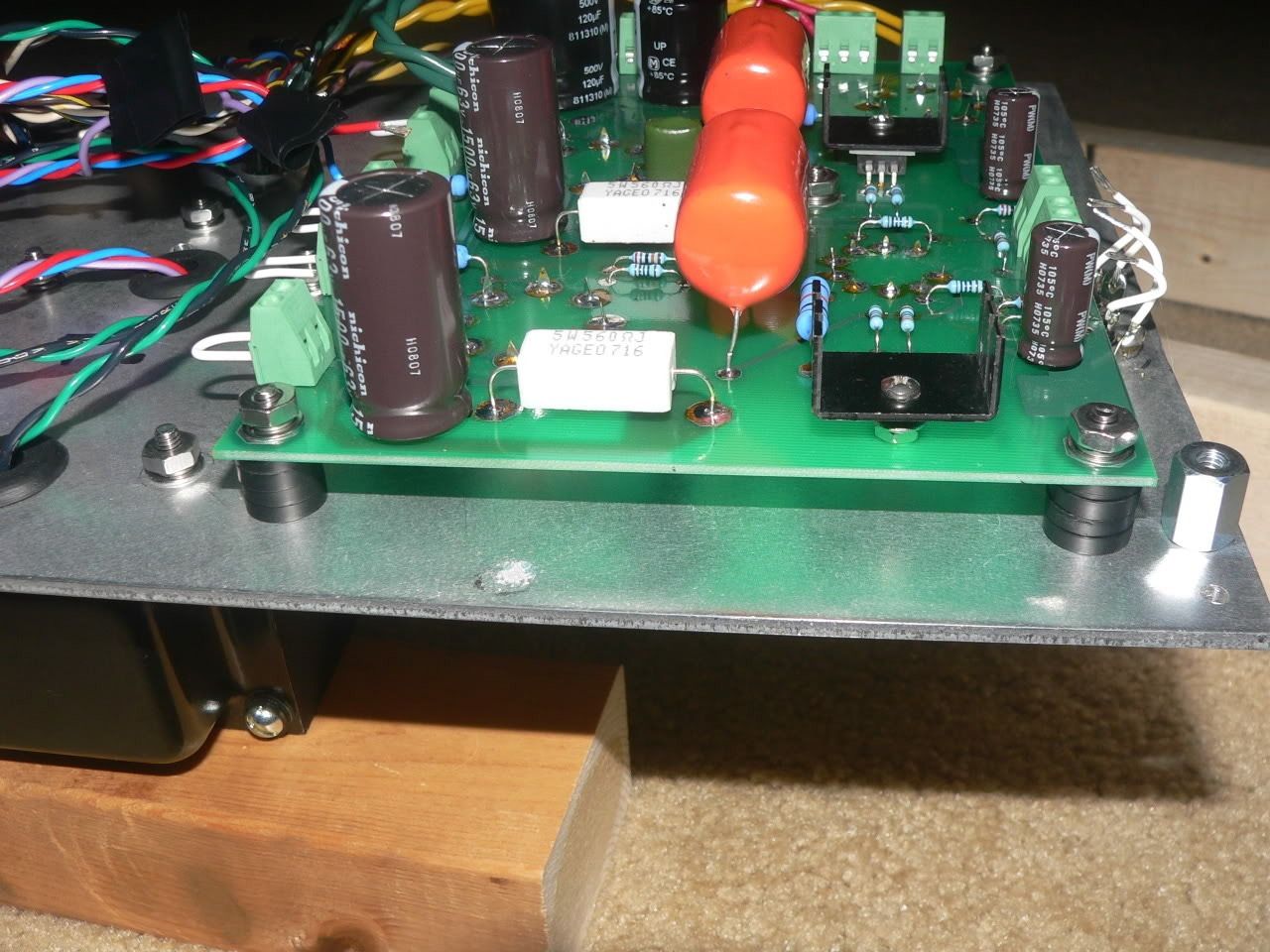
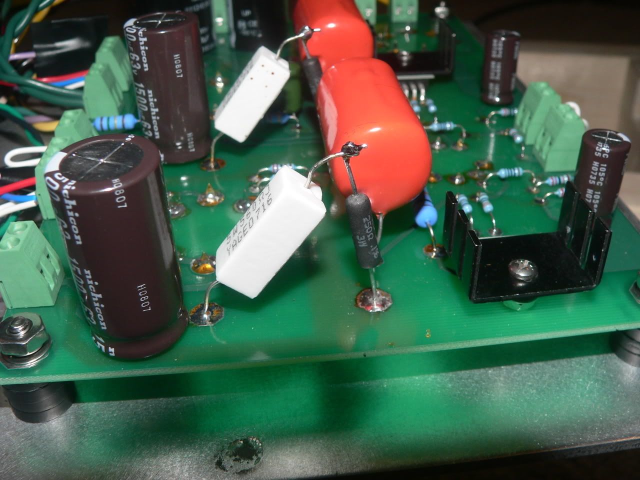
I made what I think is a worthwhile change to the way I mounted the Simple SE board to the underside of the aluminum plate. Originally I used 1/2" threaded standoffs to attach the board. These stupid things cost me $1.22 each at Mouser. I've since taken them out and now I'm using four 00 flat faucet washers over a 1" #8 machine screw. The faucet washers were $1.50 for a box of ten - I needed two boxes. It looks something like this now that it's all together. You can see one of the threaded standoffs all the way to the right edge of the photo.
I also put a thin rubber washer on the top side of the chassis plate. I would have used another thin rubber washer on the back side of the Simple SE board, but I was running out of screw length. Now the board's mounts are all floating on stacks of rubber washers. It's cheaper than using metal standoffs (well, it would have been if I had known up front) and it ought to provide some vibration isolation between the board and the power transformer.
Ty_Bower said:It appears to be mechanical in nature, most likely from the power tubes themselves. I'm guessing the grids jingle/rattle a bit when you shake the tube just so.
I made what I think is a worthwhile change to the way I mounted the Simple SE board to the underside of the aluminum plate. Originally I used 1/2" threaded standoffs to attach the board. These stupid things cost me $1.22 each at Mouser. I've since taken them out and now I'm using four 00 flat faucet washers over a 1" #8 machine screw. The faucet washers were $1.50 for a box of ten - I needed two boxes. It looks something like this now that it's all together. You can see one of the threaded standoffs all the way to the right edge of the photo.
I also put a thin rubber washer on the top side of the chassis plate. I would have used another thin rubber washer on the back side of the Simple SE board, but I was running out of screw length. Now the board's mounts are all floating on stacks of rubber washers. It's cheaper than using metal standoffs (well, it would have been if I had known up front) and it ought to provide some vibration isolation between the board and the power transformer.
Ty_Bower said:After installing a pair of new EH "fat bottle" 6CA7... Doing some quick math I've figured 61 mA idle current, and 24 watts total dissipation (plate and screen). It seems darn close to the rated maximum for a 6CA7, but I've been told these EH are good tubes. I see no red plate or glowing screen at the moment. I'll watch them carefully for signs of stress.
Last night I noticed signs of stress.

In a darkened room I can barely see very, very faint hints of red glow near the seams of the plate. I've been meaning to pull out the 560 ohm cathode resistors and put in something adjustable. I've got bunches of little black 3 watt rated Dale 250 ohm precision resistors. I'm thinking four of them in series will give me 1000 ohms cathode resistance. Simulation suggests that'll run the tubes at 17.5 watts total. I can short across one of the resistors to get 750 ohms (20.9 watts). If I want to run KT88, I can short across two resistors and have 500 ohms (28.0 watts). I'm trying to sketch up a tiny circuit board so I can mount the resistors on it and include little pin headers so I can use standard 2.54mm jumper caps for shorting.
Why build something simple and reliable, when you can overcomplicate things?
So I sketched this out using RS# 276-150 experimentor's board. The board itself is less than 2" x 3". The blue lines are where the 250 ohm resistors go. The green lines are the leads of the resistors, bent around to make connections as needed. The black rectangles are where the jumper caps would go over pin headers. Put a jumper cap over one set of pins and get 500 ohms. Put it over the other set and get 750. Leave it off completely and get 1000 ohms. Maybe I can try to build one this weekend.

So I sketched this out using RS# 276-150 experimentor's board. The board itself is less than 2" x 3". The blue lines are where the 250 ohm resistors go. The green lines are the leads of the resistors, bent around to make connections as needed. The black rectangles are where the jumper caps would go over pin headers. Put a jumper cap over one set of pins and get 500 ohms. Put it over the other set and get 750. Leave it off completely and get 1000 ohms. Maybe I can try to build one this weekend.
tubelab.com said:I use a simpler low tech method. Put the highest value cathode resistor that you would use in the board. Prepare some shunt resistors with aligator clips on each end. Clip them across your cathode resistors as needed when running the big tubes.
Good idea, I think I'll convert my feedback switch into a switch for KT-88/6550 or EL34s. Right now its 560r, so I can use either. I've been meaning to take the cfb switch out and hardwire it w/o cfb, but wasn't sure what to do with the switch, now I can make it useful. This would require me unplugging the amp, which I haven't done since it was finished a few months ago.
Ty_Bower said:Why build something simple and reliable, when you can overcomplicate things?
So much for complicated. I took the easy way out and just series'd a 250 ohm in there with the existing 560. I stuck the 250 on the ground side of the 560, so it'll be easy to add a switch to short out the 250 if desired.
As an added benefit, if I measure the voltage at the top of the 250, multiplying by 4 gives me the idle current.
Unbelievably stupid question here...
Spice model suggests that swapping a 6BQ5 into my amp with 810 ohms of cathode resistance would leave ~500 volts at the plate, but only burn 12.4 watts in the tube.
Is it possible that with a suitable socket adapter I might stick a 7189 equivalent in there? Or is 500V guaranteed to arc it out? Not to mention the voltage limit on the PSU caps...
I haven't as much experience exploring the upper limits of 6BQ5's or 7189's as I do with other tubes since they are not easy to find cheap. From my experience and what I have read, you won't find any that will live at 500 volts. Some may handle close to 500 volts on the plate, but the screen grid will fry.
Ty,
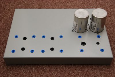
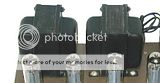
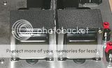
First, thanks for putting all of your build thoughts into a thread, I've referred to it frequently as I meander my way through my own simplese build. I did have one quick thought about the mechanical noise problem that you described - why not isolate the trafo mechanically from the chassis rather than floating the board? I typically do this on builds where iron and tubes are in close proximity and there's a concern of noise transmission. Here's a picture of my simple chassis as it sits right now, the blue grommets are isolation types from McMaster Carr. I can get you the part number if you're interested.
Overall Shot
Power Trafo Closeup
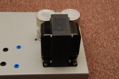
Dave,Davec113 said:n_maher, that was my strategy as well. I used 3/16" thick high density industrial felt (SAE grade F3). I cut "gaskets" for the pt, opts, and choke. Its operating temp is rated at 200 deg F, or just under 100 C.
Dave
That's a good suggestion and would clearly work as well. I just happened to have some of the grommets leftover from another project that involved some big iron. I have a soft spot for big iron.
Nate
Wow. That is a big piece of iron. 
Thanks for the comments on my project. I'm glad you like it. As far as rubber washers are concerned, I ended up using them both on the board and under the PT. I think they do the most good under the PT. I believe it's still worthwhile using them on the board if for no other reason than they are cheaper than buying the 1/2" metal standoffs. They certainly can't hurt any.
Another tip I discovered (after I finished building mine, of course) is that the "preferred" orientation of the output transformers be like those on the Eico HF-87. That is, the laminations of the OT be parallel to each other, not all in the same plane. To explain with pictures,
Do this:
Not this:
It supposedly reduces the signal induced in one OT due to stray field leaked from the other, improving channel separation.
Thanks for the comments on my project. I'm glad you like it. As far as rubber washers are concerned, I ended up using them both on the board and under the PT. I think they do the most good under the PT. I believe it's still worthwhile using them on the board if for no other reason than they are cheaper than buying the 1/2" metal standoffs. They certainly can't hurt any.
Another tip I discovered (after I finished building mine, of course) is that the "preferred" orientation of the output transformers be like those on the Eico HF-87. That is, the laminations of the OT be parallel to each other, not all in the same plane. To explain with pictures,
Do this:
An externally hosted image should be here but it was not working when we last tested it.
Not this:
An externally hosted image should be here but it was not working when we last tested it.
It supposedly reduces the signal induced in one OT due to stray field leaked from the other, improving channel separation.
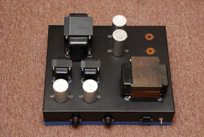
Yeah, the BFT-1B is a hunk along with the Hammond 193q choke. That power supply is, uh, not portable.
And bummer for me regarding the output trafo orientation, wish I'd known that I'd drilled all of the mounting holes. The question now is whether or not to buy another chassis or keep going with this one knowing that it's less than ideal...
And bummer for me regarding the output trafo orientation, wish I'd known that I'd drilled all of the mounting holes.
The question now is whether or not to buy another chassis or keep going with this one knowing that it's less than ideal...BFT? How clever.
I'd keep going, and not worry about it. I'm sure the difference is insignificant. Someday I'm going to put a dummy resistive load on one channel of my Simple SE, and crank a signal into the channel. Then I'll listen to see how much bleeds into the other channel. I'm betting it isn't much. There's probably a certain amount of crosstalk that occurs in the 12AT7 itself that you can't do anything about.
Besides, sometimes the theoretical ideal transformer layout isn't. I've heard of cases where people have demonstrated theoretically sub-optimal alignments, but the coupling between transformers (or lack thereof) was measurably better. Go figure.
n_maher said:And bummer for me regarding the output trafo orientation, wish I'd known that I'd drilled all of the mounting holes.
I'd keep going, and not worry about it. I'm sure the difference is insignificant. Someday I'm going to put a dummy resistive load on one channel of my Simple SE, and crank a signal into the channel. Then I'll listen to see how much bleeds into the other channel. I'm betting it isn't much. There's probably a certain amount of crosstalk that occurs in the 12AT7 itself that you can't do anything about.
Besides, sometimes the theoretical ideal transformer layout isn't. I've heard of cases where people have demonstrated theoretically sub-optimal alignments, but the coupling between transformers (or lack thereof) was measurably better. Go figure.
It's one of the more appropriate names I've come across. http://www.one-electron.com/Trans/BFT1B_11.pdfTy_Bower said:BFT? How clever.
And thanks for the words of encouragement, I hope to log some serious fab time this weekend. me =

hopefully he has some left
I have about 80 left right now. Since the recent economic meltdown sales have dropped to near zero, so they will be around for a while. If they run low, I'll get more.
Unfortunately these economic events have delayed the Simple P-P and Spud SE. The boards and parts needed to build the prototypes for testing and instruction manual photos, and the production quantity order runs between $1200 and $1600. At the current sales average of 2 boards per week, it just doesn't add up.
tubelab.com said:I have about 80 left right now. Since the recent economic meltdown sales have dropped to near zero, so they will be around for a while. If they run low, I'll get more.
Thanks George, I'll be placing an order via PayPal on Monday.
I think I'm going to be running the following on mine unless anyone sees a problem with this lineup:
Hammond 374BX Power
Hammond 193D 8 H, 150 mA Choke
Edcore XSE15-8-5K Outputs
Genalex KT88's
JJ ECC81
JJ 5AR4
- Status
- This old topic is closed. If you want to reopen this topic, contact a moderator using the "Report Post" button.
- Home
- More Vendors...
- Tubelab
- Another Simple SE builder