There's been some activity around here lately with people building out George's Simple SE board. I recently received one, and am hoping to build it out over the summer. I'm still somewhat in the planning / ordering stage right now.
I'd like to be able to run some old Coke bottle 6L6GA tubes, but I also would like to pop in some EH 6CA7 fat bottles and run them a little harder. I think I've decided to go with one of the 720~750 VCT power transformers, and just mount a switch on the first cap after the rectifier tube. I can switch between a cap input and a choke input power supply filter. If I've done the math correctly, I think I'll end up with around 450V B+ with the cap input, and just over 300V B+ with the choke input. I'm thinking either the Hammond 374BX (doesn't buzz?) or the Allied 6K7VG (inexpensive) is the way to go.
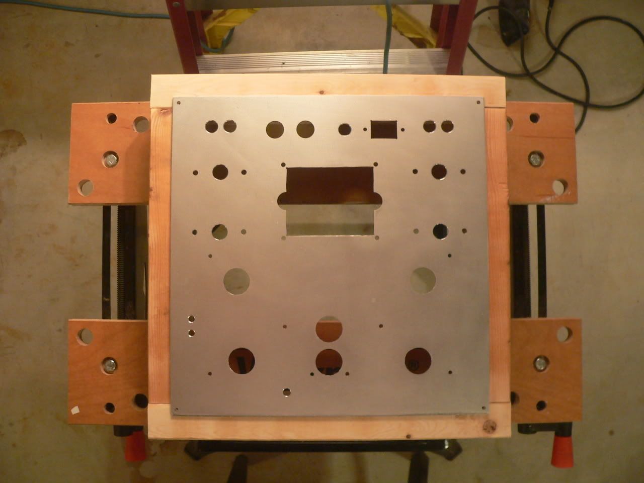
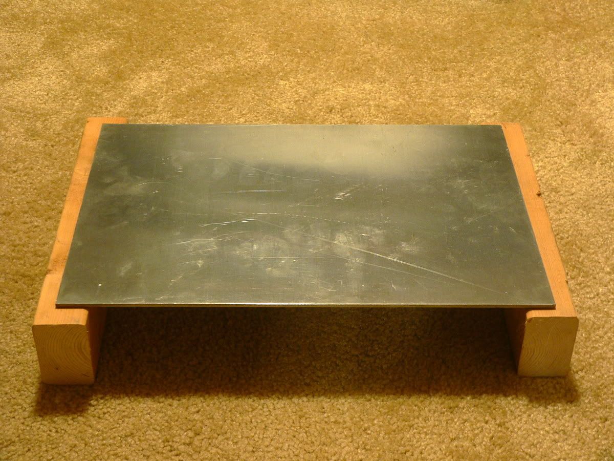
The amp I built last summer used a 1/8" aluminum top plate with a 2x4 wooden box frame. Everything was mounted in the aluminum. It was pretty easy for me to construct, even with my limited machining and woodworking skills.
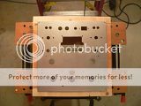
I still have a piece of that aluminum plate left, but it's a bit on the small side - about 9" x 14". I think I can squeeze everything on. I have a layout which I designed using Visio. The only piece which doesn't fit is the Triad choke. I'm hoping I can find some spare room somewhere on the side of the box frame, and just use wood screws to mount it there. I think my other option might be to mount it directly beneath the power transformer (PT on top of chassis, choke underneath). My concern is that the cores of the two would necessarily be parallel to each other, rather than the preferred (?) ninety degree angle. If you'd like to look at my chassis layout, it's attached as a PDF file. I'd appreciate any criticism.
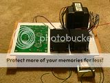
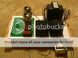
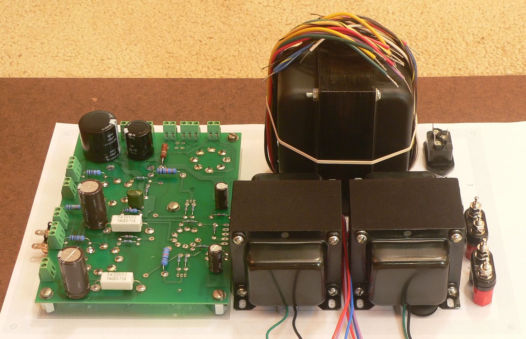
I've already received the board from George (thank you!) and ordered most of the parts from Mouser. I even got all the fiddly bits, like the switches and binding posts and RCA jacks from Mouser. If anyone is interested in my (importable) Bill of Materials, I'd be happy to share it with you. I ordered the 500V caps from DigiKey, since Mouser doesn't really stock anything suitable. I already have all the tubes, and I got a pair of the Transcendar OT from Gery.
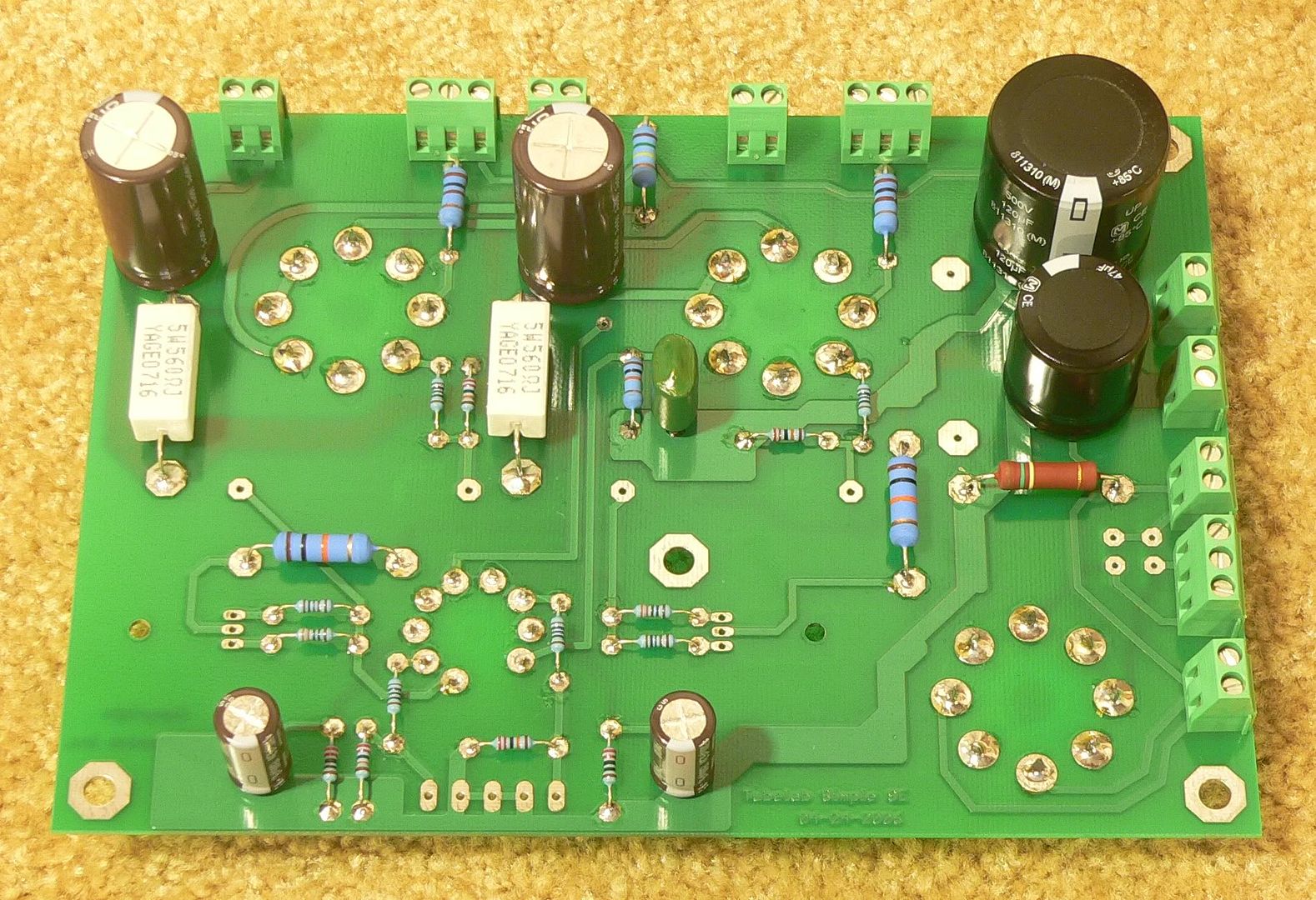
George - the next time you have a run of these boards made, please have them drill a hole through the PCB directly in the center of each tube. It would make it a lot easier to use the board as a template for chassis drilling.
I'd like to be able to run some old Coke bottle 6L6GA tubes, but I also would like to pop in some EH 6CA7 fat bottles and run them a little harder. I think I've decided to go with one of the 720~750 VCT power transformers, and just mount a switch on the first cap after the rectifier tube. I can switch between a cap input and a choke input power supply filter. If I've done the math correctly, I think I'll end up with around 450V B+ with the cap input, and just over 300V B+ with the choke input. I'm thinking either the Hammond 374BX (doesn't buzz?) or the Allied 6K7VG (inexpensive) is the way to go.
The amp I built last summer used a 1/8" aluminum top plate with a 2x4 wooden box frame. Everything was mounted in the aluminum. It was pretty easy for me to construct, even with my limited machining and woodworking skills.
I still have a piece of that aluminum plate left, but it's a bit on the small side - about 9" x 14". I think I can squeeze everything on. I have a layout which I designed using Visio. The only piece which doesn't fit is the Triad choke. I'm hoping I can find some spare room somewhere on the side of the box frame, and just use wood screws to mount it there. I think my other option might be to mount it directly beneath the power transformer (PT on top of chassis, choke underneath). My concern is that the cores of the two would necessarily be parallel to each other, rather than the preferred (?) ninety degree angle. If you'd like to look at my chassis layout, it's attached as a PDF file. I'd appreciate any criticism.
I've already received the board from George (thank you!) and ordered most of the parts from Mouser. I even got all the fiddly bits, like the switches and binding posts and RCA jacks from Mouser. If anyone is interested in my (importable) Bill of Materials, I'd be happy to share it with you. I ordered the 500V caps from DigiKey, since Mouser doesn't really stock anything suitable. I already have all the tubes, and I got a pair of the Transcendar OT from Gery.
George - the next time you have a run of these boards made, please have them drill a hole through the PCB directly in the center of each tube. It would make it a lot easier to use the board as a template for chassis drilling.
Attachments
I am dealing with the same issues of trying to layout the board and get the positions right for the holes. Does anyone have measurements for the center of the tube holes on the SimpleSE board? I already soldered my components so it is hard to measure them accurately.
If ya'll haven't stuffed your boards yet, plop it on a photocopier make a copy. Just be sure the copier doesn't change the scale of the copy. Makes for a great template.
ciagon said:Does anyone have measurements for the center of the tube holes on the SimpleSE board? I already soldered my components so it is hard to measure them accurately.
Here's a hint for the next "PCB under chassis" amp you build: Only solder one leg of each tube socket. Then cut your chassis' top plate, and mount the board. Now you can wiggle each socket until they line up perfectly with the chassis holes. When they're aligned to your satisfaction, solder the remaining legs on each socket.
Or just cut the chassis holes plenty big so there's no chance of missing...
I'm very slow to build. Sorry.
I've acquired all the glass, iron, and parts. Only thing I might be missing now is a few pieces of wood to build a box frame. Oh, and the finishing. I'm missing that too.
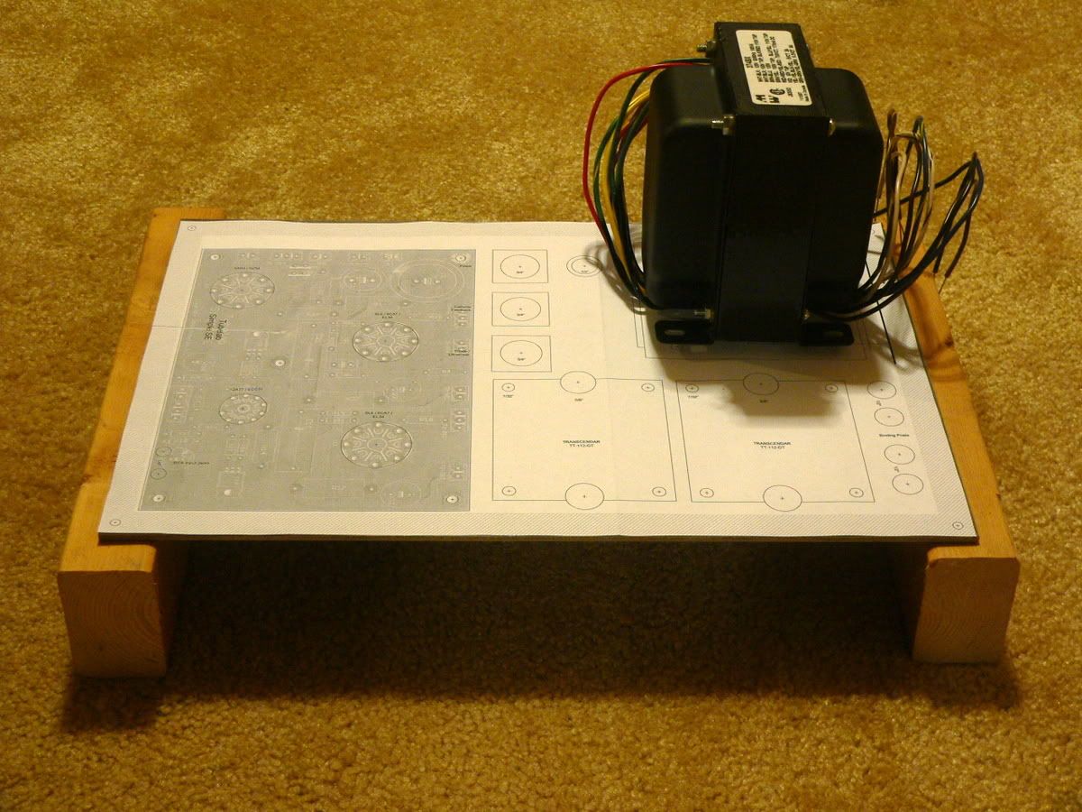
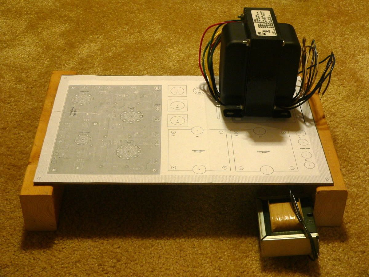
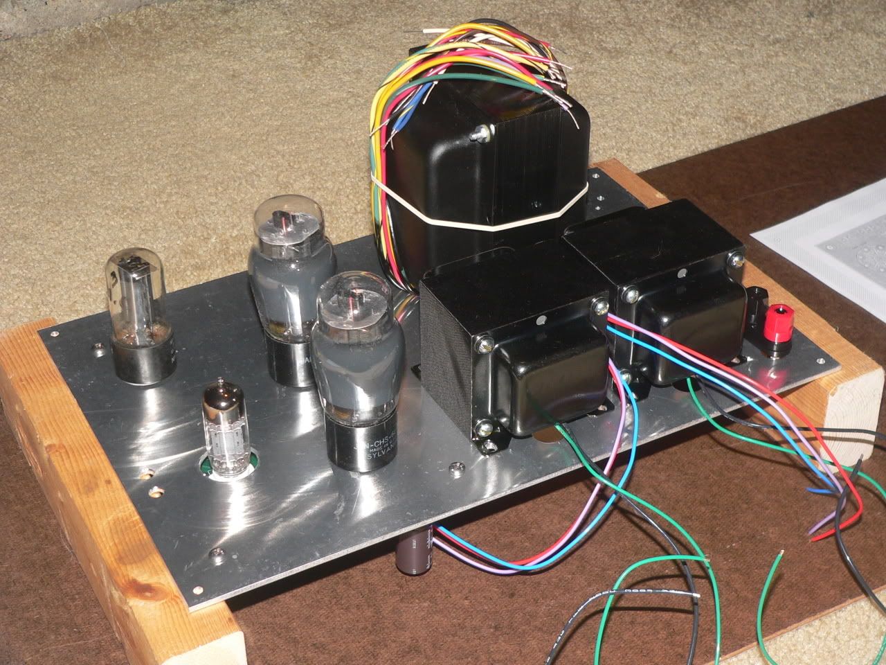
Here's my plan. Wood box frame, aluminum top plate chassis punched for mounting the board underneath. I've got the layout done in Visio. I think it's going to look something like this when it's done:

Aluminum plate and wood. There will be another piece of wood along the front and back, too.
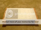
Add a paper template on top for the drill guide.
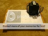
Power transformer goes here.
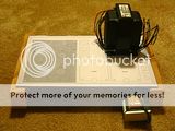
Filter choke will hide under the chassis, directly beneath the PT. It gets screwed to the wood frame.
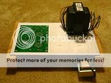
Populated Simple SE board goes on the left, under the chassis using 1/2" standoffs.
Transcendar output transformers sit up front. Binding posts will sit on the far right.
A couple of power tubes propped up in their approximate locations to give a feel for the finished amp.
Any recommendations before I start drilling?
I've acquired all the glass, iron, and parts. Only thing I might be missing now is a few pieces of wood to build a box frame. Oh, and the finishing. I'm missing that too.
Here's my plan. Wood box frame, aluminum top plate chassis punched for mounting the board underneath. I've got the layout done in Visio. I think it's going to look something like this when it's done:
Aluminum plate and wood. There will be another piece of wood along the front and back, too.
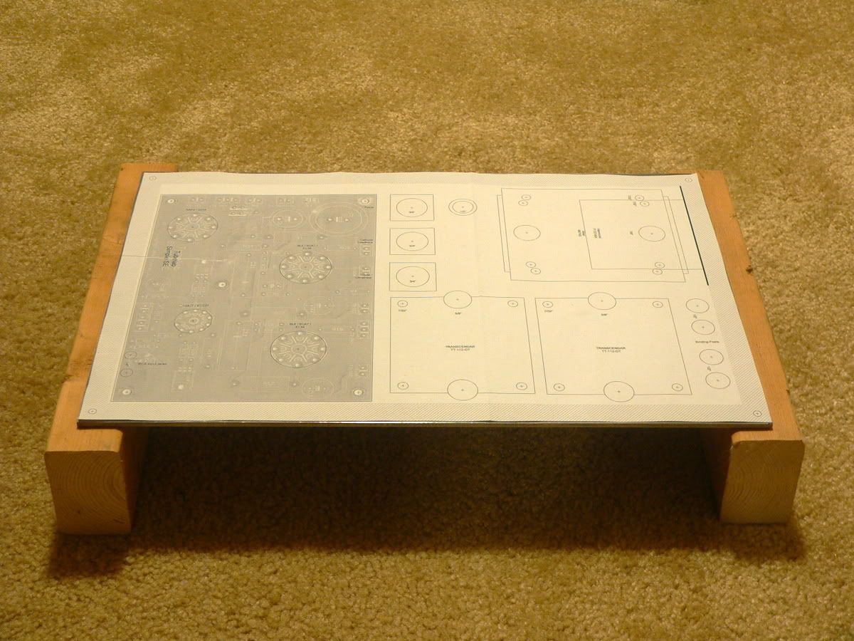
Add a paper template on top for the drill guide.
Power transformer goes here.
Filter choke will hide under the chassis, directly beneath the PT. It gets screwed to the wood frame.

Populated Simple SE board goes on the left, under the chassis using 1/2" standoffs.

Transcendar output transformers sit up front. Binding posts will sit on the far right.
A couple of power tubes propped up in their approximate locations to give a feel for the finished amp.
Any recommendations before I start drilling?
great stuff! keep us updated- I am at the stage where I am about to solder- but I need to plan chassis layout-- Thank you for the pdf as well that will be very useful for myself and other newbies in the planning stage-where did you get the coke if u dont mind me asking?
The choke and the power transformer are both Hammond. I ordered them from Antique Electronic Supply (tubesandmore.com).
I moved things around a little since I posted the .pdf of the chassis layout. I decided I hadn't left enough room on one edge of the Simple SE board to get the leads into the Phoenix blocks. I wish the aluminum plate I have were just a 1/2" bigger in each direction. I feel like it's just a little bit more cramped than I'd like. I've got no good place to put the RCA input jacks as it is right now.
I moved things around a little since I posted the .pdf of the chassis layout. I decided I hadn't left enough room on one edge of the Simple SE board to get the leads into the Phoenix blocks. I wish the aluminum plate I have were just a 1/2" bigger in each direction. I feel like it's just a little bit more cramped than I'd like. I've got no good place to put the RCA input jacks as it is right now.
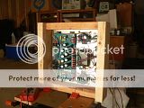
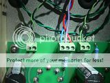
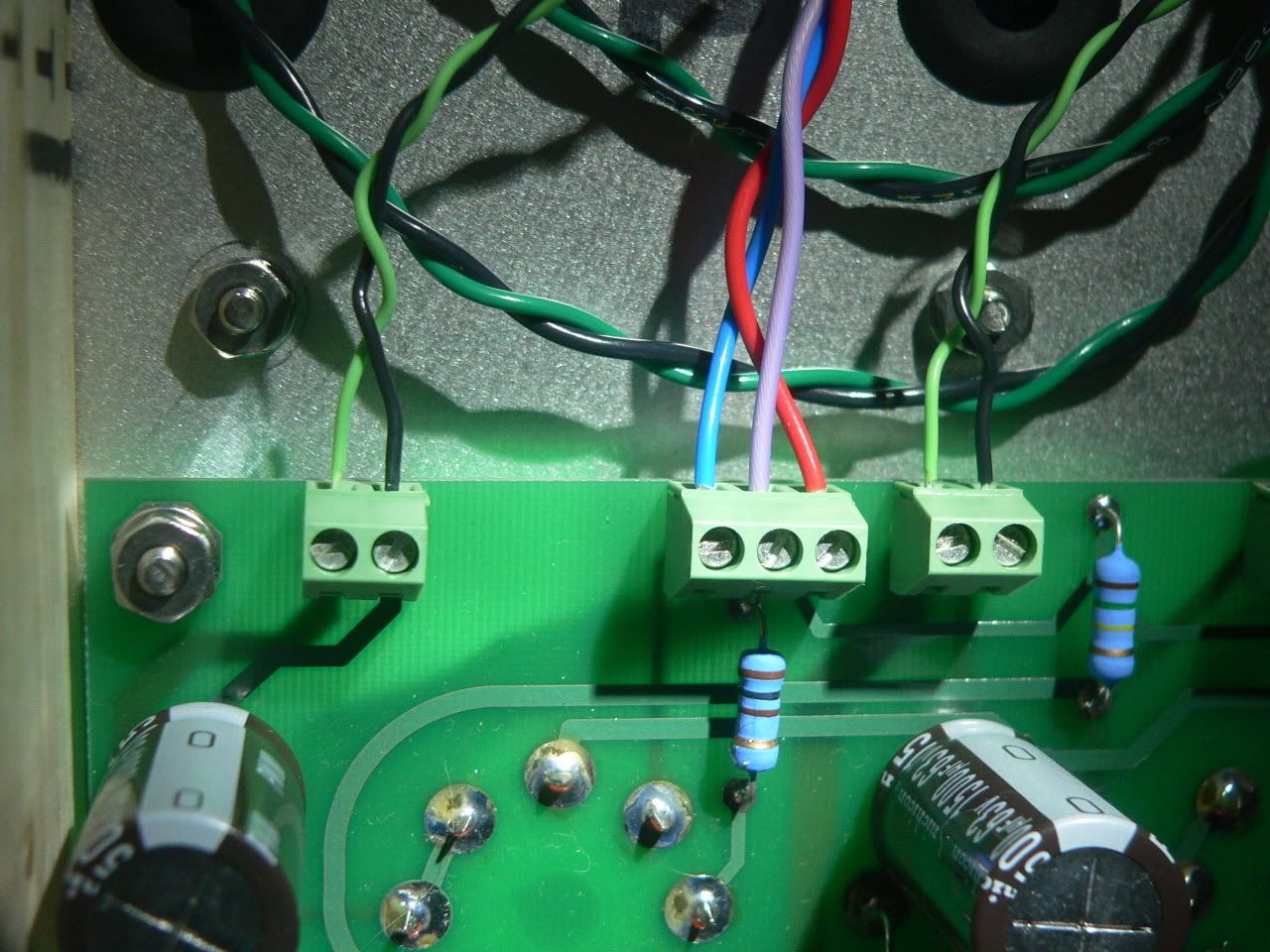
Did most of the soldering tonight. I still need to install the voltage regulators, and the last few Phoenix blocks. I wish I had bought a five pin block instead of 2 two pin blocks for the inputs. Oh well. I also need to decide on the coupling caps. I've got some nice K40Y that I'd like to use, but they're huge.
I'll drill out the chassis today. I checked the layout one last time before drilling. I scooted the PT over to the left so it's symmetrical with the OTs. Noticed I used the wrong template for the PT footprint, so I need to fix that and reprint (used the Allied instead of the Hammond). I also moved the board over 1/4" to the right to make room for the RCA input jacks at the far left.
In retrospect, I wish I had put all the small resistors on the other side of the board. Originally I wanted every component to be accessible without having to unbolt the board from the chassis, but now I wish I had the space to try to fit in my big coupling caps. Oh well.
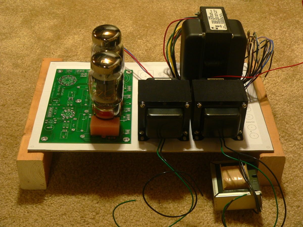
How close can I get a KT88 to an OT? This is a small chassis, and I'm not going to have a lot of clearance between the front power tube and the left transformer. Maybe 3/4" at best...
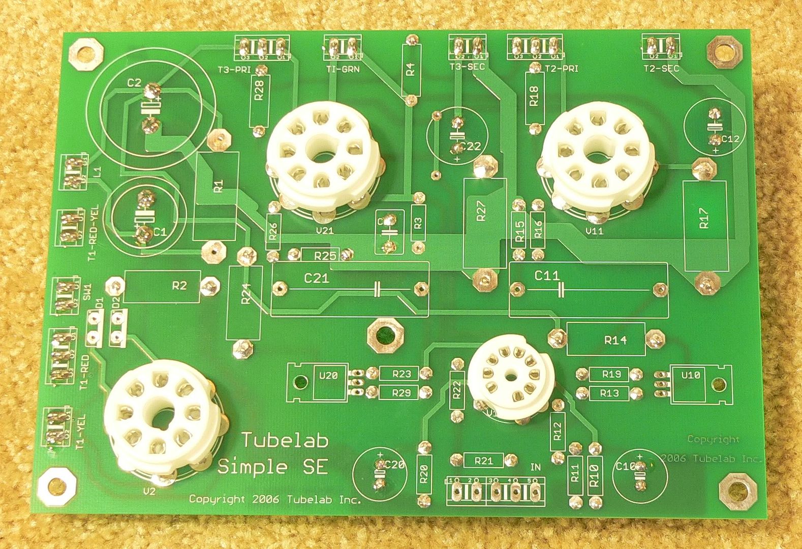
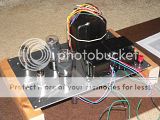
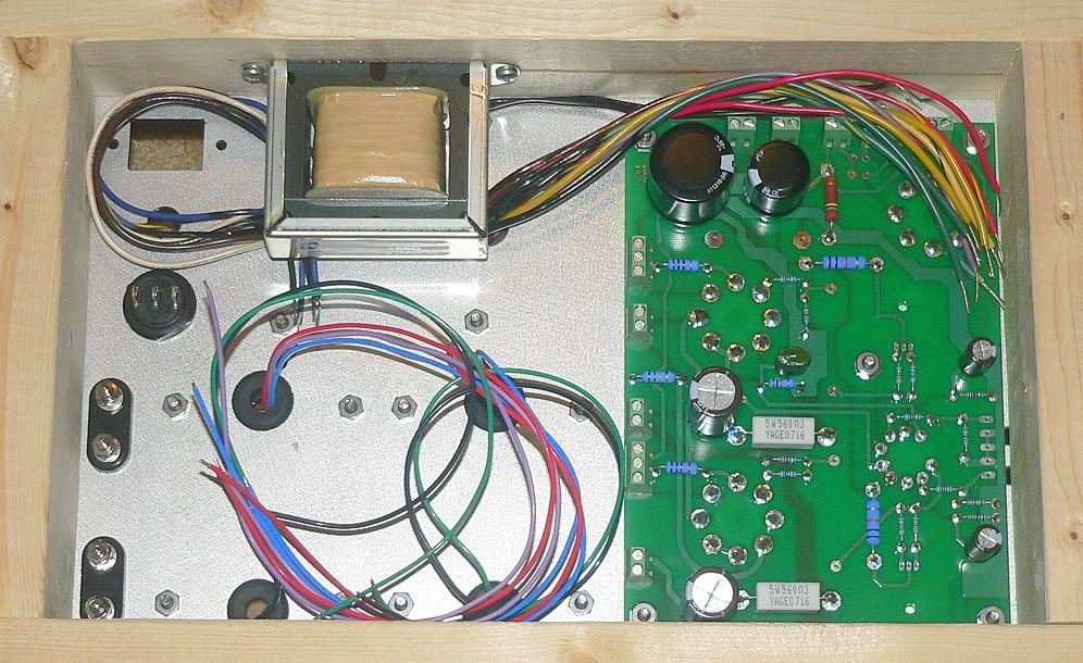
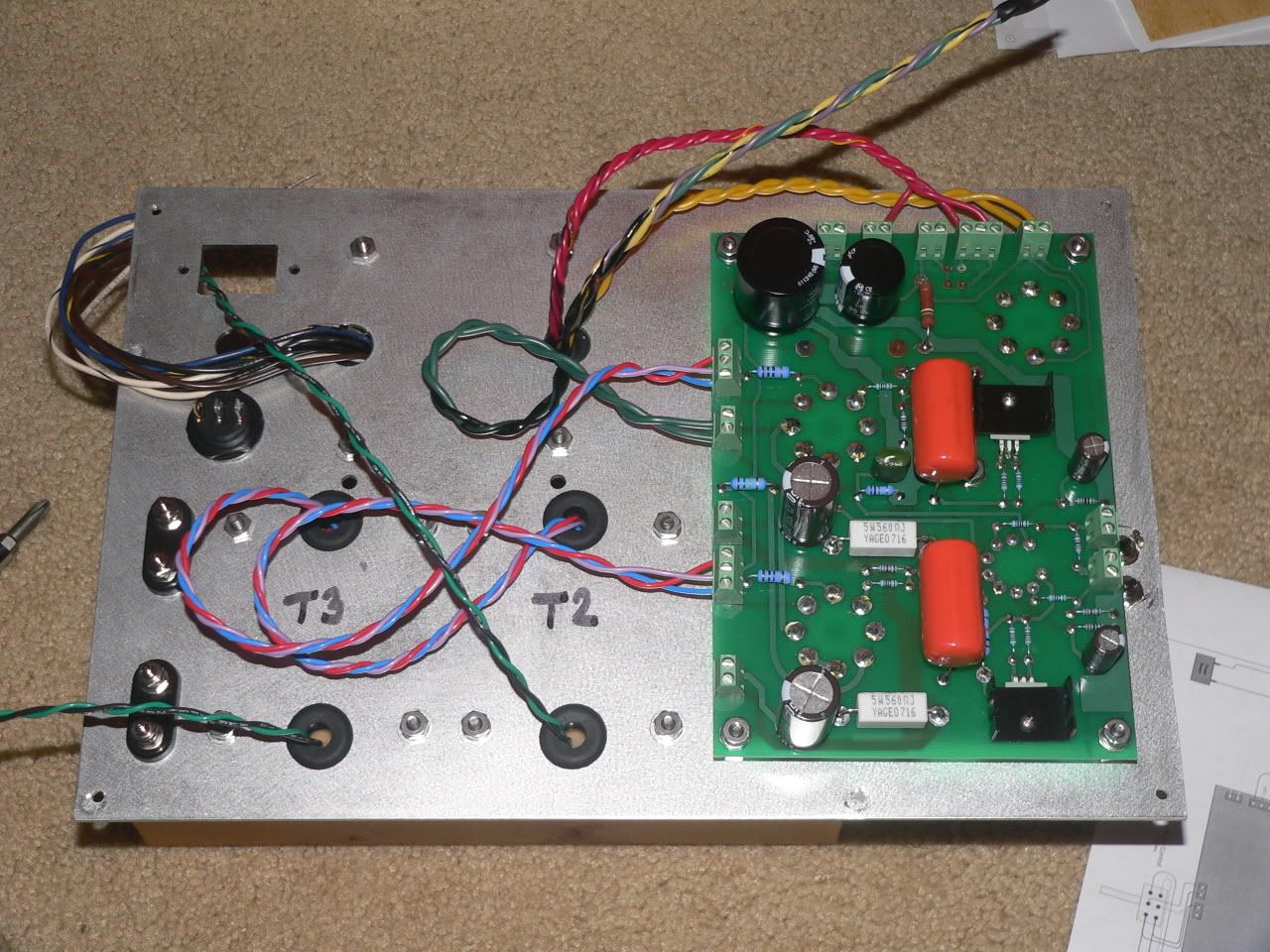
The board is upside down in the photo. It'll get mounted right side up, underneath the chassis top plate after everything is drilled out.
In retrospect, I wish I had put all the small resistors on the other side of the board. Originally I wanted every component to be accessible without having to unbolt the board from the chassis, but now I wish I had the space to try to fit in my big coupling caps. Oh well.
How close can I get a KT88 to an OT? This is a small chassis, and I'm not going to have a lot of clearance between the front power tube and the left transformer. Maybe 3/4" at best...
The board is upside down in the photo. It'll get mounted right side up, underneath the chassis top plate after everything is drilled out.
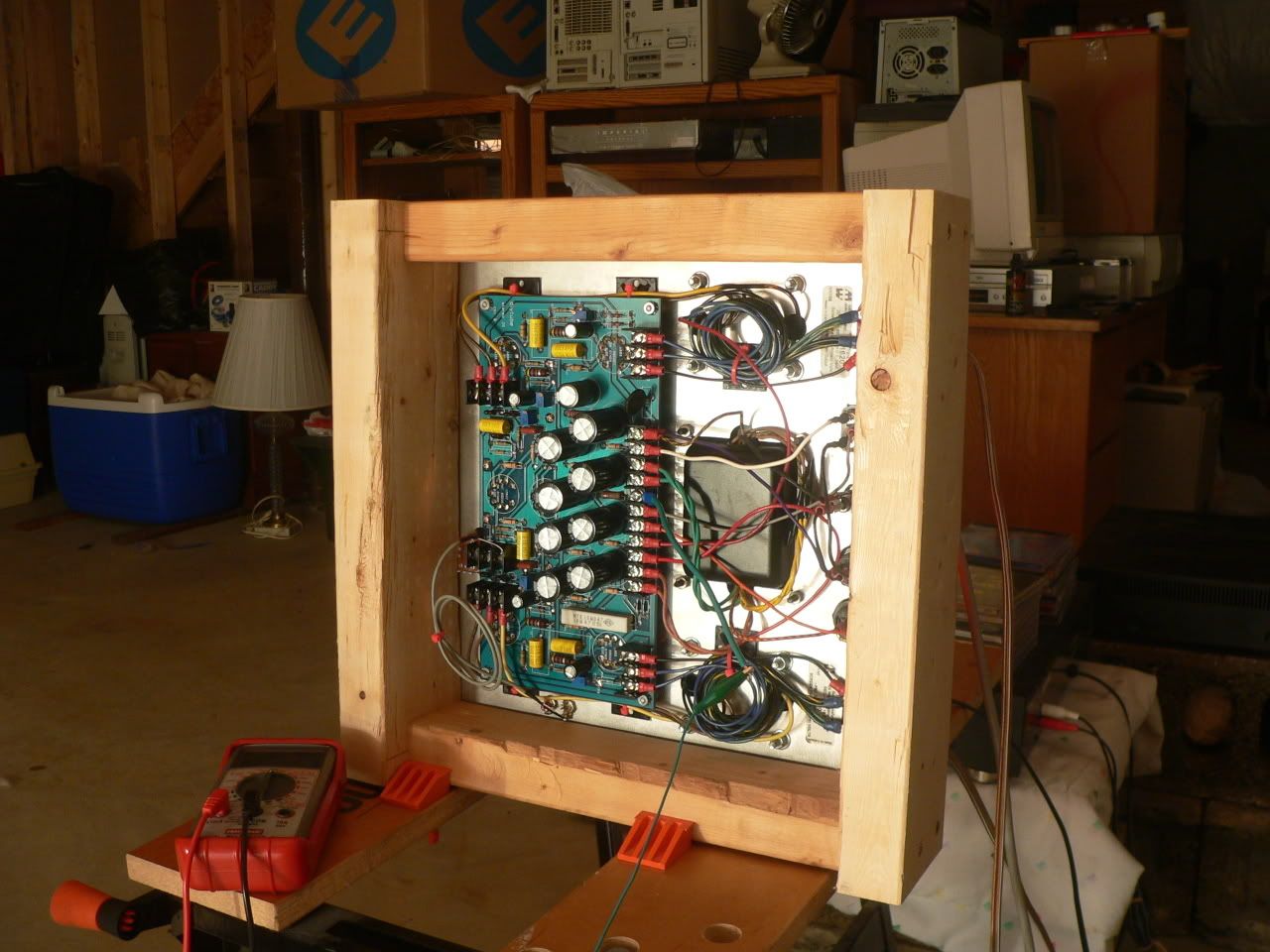
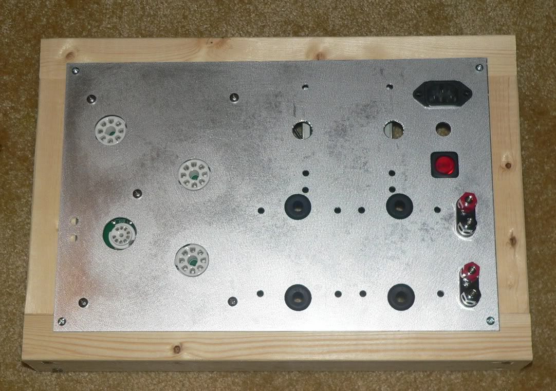
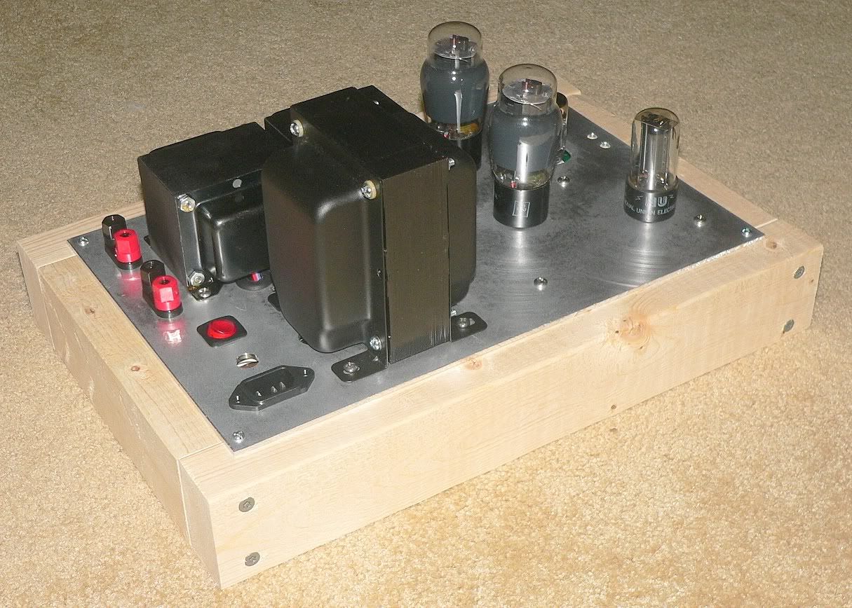
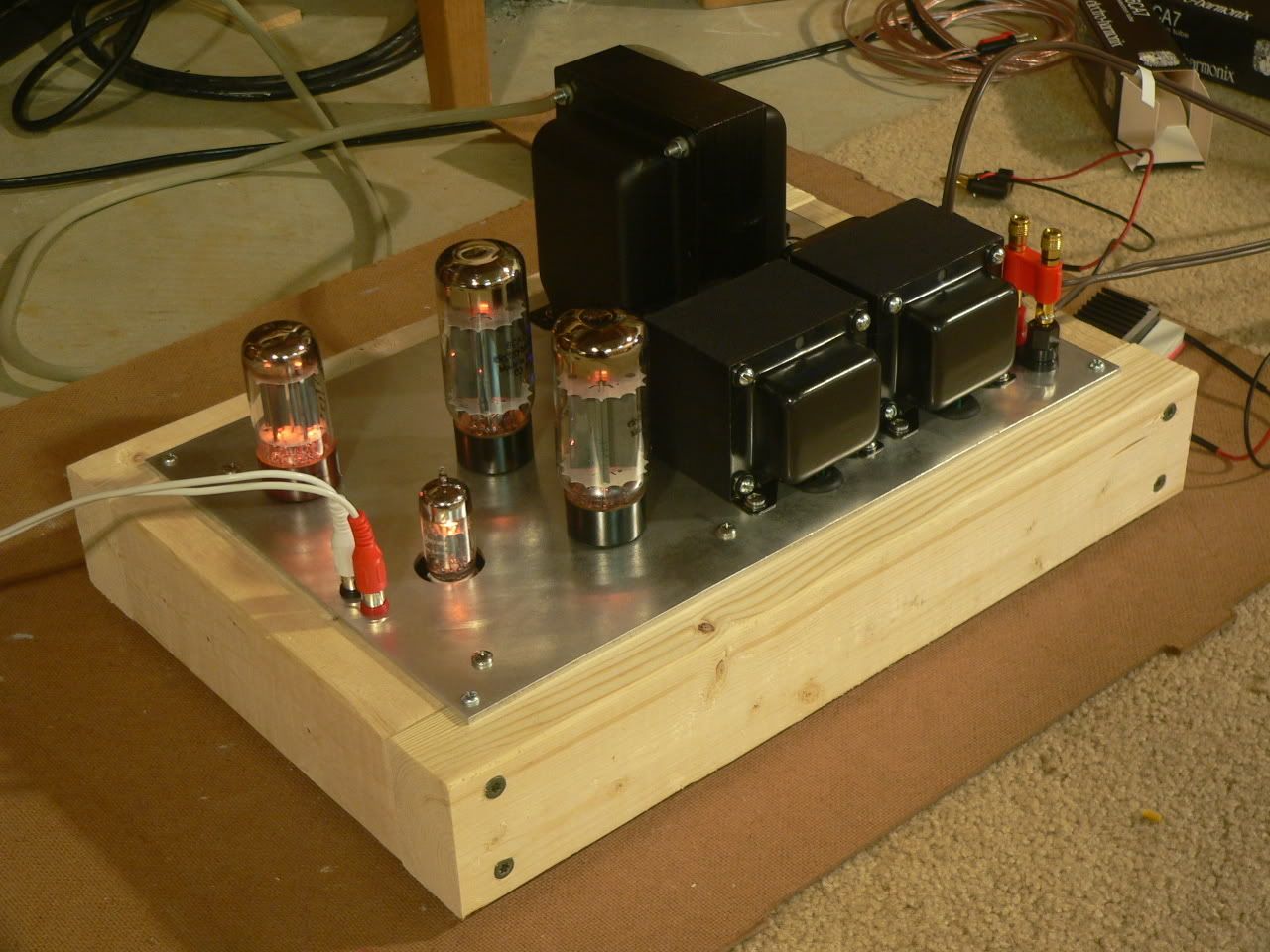
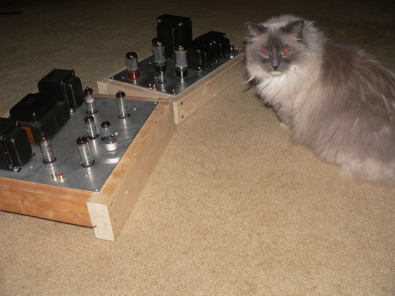
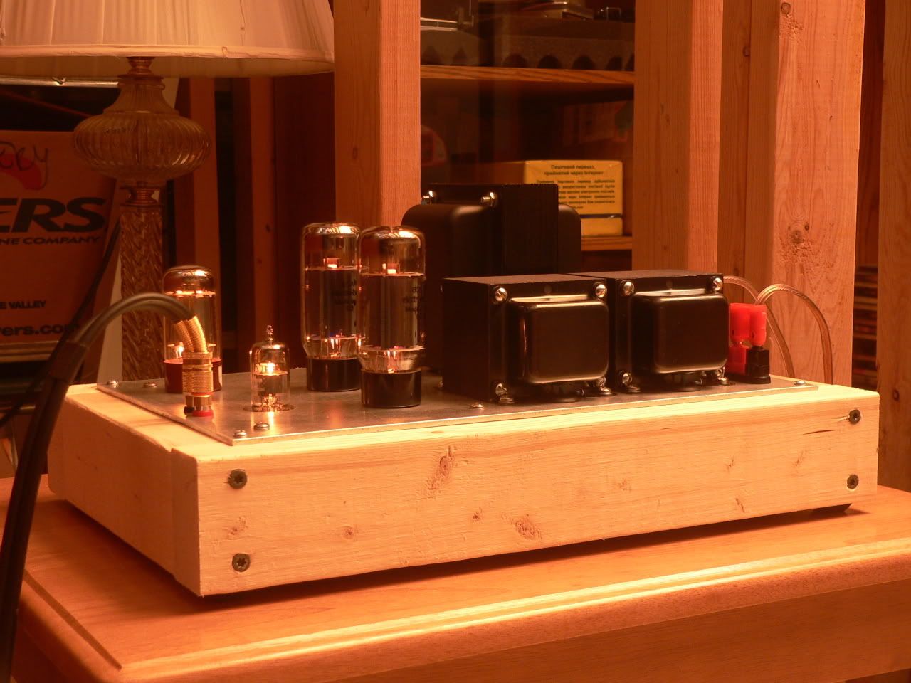
Still much to do, but at this point I think it's more done than not. The wood box frame needs to be made, and the chassis top plate needs to be sanded to get out the scratches. I can't decide if I want to powercoat it black. After that, there's the wiring to do.
I think the chassis top plate turned out just fine. 🙂
I think the chassis top plate turned out just fine. 🙂


The listening part comes soon. I put the last few components on the board (current regulators, coupling caps, input connectors).
I had some trouble with the current regulators - after bending the three leads as directed, the mounting hole didn't line up. Rather than try to re-bend the leads closer to the TO-220 package, I used the Dremel tool to cut the mounting hole a little longer. Perfect fit.
I wanted to use my K40Y caps but they seemed just too big. I settled for some 715P Orange Drops I had leftover from a previous project.
I got 80% through the wiring tonight. I still have to finish the line side of the power transformer, and there are a few little jumpers to get installed for the RCA input jacks. My wiring looks a little spaghetti. I should probably cut the excess off the transformer leads, but for some reason I can't bring myself to do it.


I should probably cut the excess off the transformer leads, but for some reason I can't bring myself to do it.
Make it work first. Then the wires will be eaiser to cut!
Can anyone who has used the Transcendar output transformers say with any confidence which way the cathode feedback connections should be made? On George's wiring diagrams he suggests that many of the OPTs he has used require the black lead from the OPT to be connected towards the end of the board closest to the power supply caps and rectifier tube. I've guessed that mine should be connected this way, but it would be nice to hear from someone who has already used the Transcendars on a Simple SE.
What's the recommended rating for the fuse? Slow blow, or fast?
What's the recommended rating for the fuse? Slow blow, or fast?
Well, that was easy. But, I won't get a chance to really listen to it until after the kids are all put to bed tonight...
I have a Simple SE with Transcendars in it. I can check it out when I get home. I should be there maybe tomorrow (currently in a cheap hotel on I-95). More cancer surgery on Tuesday and tropical storm Fay should also be there on Tuesday. I might not get time to take the cover off of the amp, for a day or two.
Well, I'm finally getting a little time to play with my new toy.
I did some voltage checks. The PT is 395-0-395 with no load (pulled the rectifier tube). The 5 volt and 6.3 volt windings appeared to be spot on. Line voltage is 120 tonight, which is a hair lower than usual.
After installing a pair of new EH "fat bottle" 6CA7 and a Ruby (Chinese) rectifier 5AR4, B+ is about 455V. I'm seeing 433 volts at the anodes and about 442 volts at the screens. Both cathodes are fairly closely matched at 34 volts. Doing some quick math I've figured 61 mA idle current, and 24 watts total dissipation (plate and screen). It seems darn close to the rated maximum for a 6CA7, but I've been told these EH are good tubes. I see no red plate or glowing screen at the moment. I'll watch them carefully for signs of stress.
I verified proper connection of the cathode feedback. I tried it both ways, and watched the output voltages on my 'scope. I have no doubt it is connected correctly. The wiring is as I had guessed it ought to be originally. The secondary's green wire must be landed furthest from the rectifier / power supply cap side of the board. By the way, has anyone noticed that you can very clearly hear the audio material emanating directly from the tubes themselves? I had dummy 8 ohm loads connected during feedback testing, and I was surprised the music was so audible. I don't recall noticing the effect with the smaller 6BQ5 tubes.
I've got a slight hum issue, which I've temporarily corrected. My RCA input jacks are not isolated from the aluminum top plate of the chassis. On the far other end of the chassis, I've attached the IEC power connector's safety ground. My other amp was built the same exact way, and it didn't hum. Guess I wasn't so lucky this time. I need to work out a permanent fix, which will most likely involve isolating the RCA input jacks from the chassis.
The amp has quite a bit more gain than the Dynaco ST35 clone to which I am accustomed. I tend to listen late at night, I have sleeping kids, and I usually keep the volume low. My Paradigm 7se Mk3 are relatively efficient, at least >90dB. I'm finding the Simple SE requires me to keep the volume knob on my preamp really close to the bottom. I'm not sure what I'm going to do here, or if this is even an issue.
There's a bit more hiss (or rushing noise) which I didn't see in my ST35. It doesn't bother me near half as bad as hum, and I'll easily ignore it. I'm assuming it has something to do with the much higher gain of this amp (or possibly the much lower quantity of feedback used).
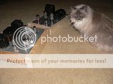
I really like the looks of my layout, and I'm really happy with this build. I tell myself someday I'll stain and poly the wood frame, but it's been a year and I still haven't finished my ST35. In my opinion, the rough and natural look is more pleasing visually and encourages the owner to appreciate more time enjoying the sound. Apparently, my cat concurs.

All in all, a good build and highly recommended.
I did some voltage checks. The PT is 395-0-395 with no load (pulled the rectifier tube). The 5 volt and 6.3 volt windings appeared to be spot on. Line voltage is 120 tonight, which is a hair lower than usual.
After installing a pair of new EH "fat bottle" 6CA7 and a Ruby (Chinese) rectifier 5AR4, B+ is about 455V. I'm seeing 433 volts at the anodes and about 442 volts at the screens. Both cathodes are fairly closely matched at 34 volts. Doing some quick math I've figured 61 mA idle current, and 24 watts total dissipation (plate and screen). It seems darn close to the rated maximum for a 6CA7, but I've been told these EH are good tubes. I see no red plate or glowing screen at the moment. I'll watch them carefully for signs of stress.
I verified proper connection of the cathode feedback. I tried it both ways, and watched the output voltages on my 'scope. I have no doubt it is connected correctly. The wiring is as I had guessed it ought to be originally. The secondary's green wire must be landed furthest from the rectifier / power supply cap side of the board. By the way, has anyone noticed that you can very clearly hear the audio material emanating directly from the tubes themselves? I had dummy 8 ohm loads connected during feedback testing, and I was surprised the music was so audible. I don't recall noticing the effect with the smaller 6BQ5 tubes.
I've got a slight hum issue, which I've temporarily corrected. My RCA input jacks are not isolated from the aluminum top plate of the chassis. On the far other end of the chassis, I've attached the IEC power connector's safety ground. My other amp was built the same exact way, and it didn't hum. Guess I wasn't so lucky this time. I need to work out a permanent fix, which will most likely involve isolating the RCA input jacks from the chassis.
The amp has quite a bit more gain than the Dynaco ST35 clone to which I am accustomed. I tend to listen late at night, I have sleeping kids, and I usually keep the volume low. My Paradigm 7se Mk3 are relatively efficient, at least >90dB. I'm finding the Simple SE requires me to keep the volume knob on my preamp really close to the bottom. I'm not sure what I'm going to do here, or if this is even an issue.
There's a bit more hiss (or rushing noise) which I didn't see in my ST35. It doesn't bother me near half as bad as hum, and I'll easily ignore it. I'm assuming it has something to do with the much higher gain of this amp (or possibly the much lower quantity of feedback used).
I really like the looks of my layout, and I'm really happy with this build. I tell myself someday I'll stain and poly the wood frame, but it's been a year and I still haven't finished my ST35. In my opinion, the rough and natural look is more pleasing visually and encourages the owner to appreciate more time enjoying the sound. Apparently, my cat concurs.
All in all, a good build and highly recommended.
- Status
- Not open for further replies.
- Home
- More Vendors...
- Tubelab
- Another Simple SE builder