
Technology can be the same but if his voice to the character of the same?
But Vishay for me too smooth and polite .... less bright.
If you have tried vishay TX2575, for me this resistor not "too smooth" but neutral and full of detail also add some more deep bass
recently today I replaced Takman metal film from my 300B tube amp with TKD correctohm CM series, the result is more cleaner high and bit lower noise floor
Last edited:
Resistor upgrade Vishay
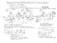
Well I just put in some rca jumpers from my current Loesch preamp (schematic attached) to allow the replacement of its partially shunted Daven non-inductive stepped attentuator with the Placette Remote volume control. The Placette utilizes something like 17 TX2352 (S102) resistors per channel with some electronics wizardry to achieve 125 steps. Despite dropping from a 20k pot to a nearly 9k load in the Placette, the results have been jaw dropping. The bass has become incredibly dynamic with absolutely wicked treble transient reproduction. Frankly, the degree of change has been more than I've experienced in any previous equipment change. Needless to say I am intrigued by the sound of resistors after this, though I expect that much of this difference is due to the zero inductance of the bulk foil versus the slight inductance of the non-inductive wirewounds.
Outside of the Loesch, I also have 250k pot on a tube midrange amp and something like a 10k pot in an active subwoofer crossover. i previously have had some load resistors changed without a great change in sound and have enen put in fixed values for the 250k pot before. The changes in sound have been minor.
With the tx2352(s102) in Placette I do sense midrange issues on line sources like a cd player, but when I use the phono stage then I am not totally positive about the bulk foil sound. To my ears, I need more of that sound in the unit to increase performance at the extremes so it may keep up with thunderous Blu-ray's and CDs. But, my guess is that the TX2575 is the solution here, or the midrange may suffer too much with the brutally accurate s102 sound. The unit currently utilizes very nice vintage resistors, non-inductive wirewounds when possible and even some allen Bradley's here and there.
I am inclined to go after the 10 ohm resistors (unit has 30.5 ohm in place) in series with the signal path (grid resistors). But, I thought I'd post this up here for some expert advice. Most of the rest of the phono circuitry would effect the EQ and I don't have immediate plans to mess with those components (resistor suggestions welcome). The unit is a bit difficult to work on so I'd rather do the changes in batches rather than one at a time, so eager to find out what to attack and where the TX2575 might best be exploited. I am pretty sure that the 30.5 ohm resistors are vintage Allen Bradley carbon composition resistors.... in the line stage, in the phono they are some very vintage non-inductive Daven wirewounds ribbed for her pleasure.
Attachments
Resistors tryouts
Hi guys,
I just found your thread. Very interesting discussions. Different points of vue, a lot to learn.
On a similar topic, we are doing a lot of "resistors tryouts" in the following thread, should you be interested in the results.
http://www.diyaudio.com/forums/analog-line-level/252030-salas-hotrodded-dcb1-resistor-tryouts.html
Regards
Scorpion
The 30r5 is a grid stopper (is that the correct term in tube/valve?)
As a grid stopper, it does not matter that it's resistance varies dynamically with signal.
It is effectively not part of any NFB gain setting function, again resistance variation can be tolerated.
The most important characteristic for a "stopper" resistor is ultra low inductance, no helical turns. Carbon composition is ideal for this.
For all other duties carbon resistors usually degrade amplifier performance.
It is not surprising that ultra stable resistors appear to perform better for the parts of the circuit that require that characteristic.
And not surprising that carbon has been chosen as stoppers for best performance..
There are 10r doing the same duty at the other end of the amp.
Are these carbon composition?
Is your proposed replacement for the 30r5 also carbon composition?
If I am reading your sch correctly there looks to be no global feedback.
That would mean that each stage must use it's local feedback to "fix" the gain and the performance into each stage.
Stability of resistor values in the local feedback are just as important as those in a global loop. High performance comes from high stability.
Last edited:
People often say this. I suspect they have never built anything using RF. In RF we sometimes use a stopper which has lots of inductance, but also enough resistance to damp the resonance. Resistance is what does it, not lack of inductance. Inductance merely shifts the frequency of the unwanted resonance downwards - which in most cases would be a good thing as it reduces coupling.AndrewT said:The most important characteristic for a "stopper" resistor is ultra low inductance, no helical turns. Carbon composition is ideal for this.
You could probably even use a small wirewound as a grid stopper! The only requirement is that remains lossy up to VHF/UHF frequencies; it doesn't have to be purely resistive.
Resistance is what does it
AC resistance of carbon resistors goes down at high frequencies. The higher the value, the faster the drop.
A large value grid stopper in carbon is likely a rather poor choice.
Grid stopper, etc.
The original Loesch design (which is handwritten) used 10 ohm Mills noninductive wirewounds (the M in the schematic means Mills in the legend which is a bit confusing since we have Megaohms too). I am sure that the 30.5 ohm Daven noninductive wirewounds were chosen for the phono stage because that was the closest value on hand and perhaps carbon might be too noisey. Based on what you say, I suspect switching the Davens to Vishay bulk foil would be an improvement since the Daven despite being a noninductive wirewound, still would have some inductance. In the line stage the carbon grid stopper should stay for now since that is actually in another box and who knows it may just work very well for that special sonic signature (in the schematic, from the selector switch back is actually in a seperate line stage box).
I've done the RIAA formulas for much of the phono stage circuitry and may end up redoing this part of the circuit when I try to upgrade capacitors. I am not sure what is best for the plate resistors here which are all higher wattage. At this point I am looking for some low hanging fruit that might allow improvement without just blindly throwing in expensive bulk foil resistors that en masse may develop problems of their own. I will try to get into the line stage section as I can remove the bulky Daven 20k pots as I am outboarding the Placette Remote Volume Control now. This may make the board extremely accessible with a few more changes (no desoldering necessary just unmounting board.)
Thanks for the response! The grid stoppers at the other end (line stage) are Allen Bradley carbons. I am not as intimittenly familiar with the actual parts as most of the line stage circuitry is around the base of the tube sockets and is not easily viewed without completely removing the mounting board. There is no global feedback.The 30r5 is a grid stopper (is that the correct term in tube/valve?)
As a grid stopper, it does not matter that it's resistance varies dynamically with signal.
It is effectively not part of any NFB gain setting function, again resistance variation can be tolerated.
The most important characteristic for a "stopper" resistor is ultra low inductance, no helical turns. Carbon composition is ideal for this.
For all other duties carbon resistors usually degrade amplifier performance.
It is not surprising that ultra stable resistors appear to perform better for the parts of the circuit that require that characteristic.
And not surprising that carbon has been chosen as stoppers for best performance..
There are 10r doing the same duty at the other end of the amp.
Are these carbon composition?
Is your proposed replacement for the 30r5 also carbon composition?
If I am reading your sch correctly there looks to be no global feedback.
That would mean that each stage must use it's local feedback to "fix" the gain and the performance into each stage.
Stability of resistor values in the local feedback are just as important as those in a global loop. High performance comes from high stability.
The original Loesch design (which is handwritten) used 10 ohm Mills noninductive wirewounds (the M in the schematic means Mills in the legend which is a bit confusing since we have Megaohms too). I am sure that the 30.5 ohm Daven noninductive wirewounds were chosen for the phono stage because that was the closest value on hand and perhaps carbon might be too noisey. Based on what you say, I suspect switching the Davens to Vishay bulk foil would be an improvement since the Daven despite being a noninductive wirewound, still would have some inductance. In the line stage the carbon grid stopper should stay for now since that is actually in another box and who knows it may just work very well for that special sonic signature (in the schematic, from the selector switch back is actually in a seperate line stage box).
I've done the RIAA formulas for much of the phono stage circuitry and may end up redoing this part of the circuit when I try to upgrade capacitors. I am not sure what is best for the plate resistors here which are all higher wattage. At this point I am looking for some low hanging fruit that might allow improvement without just blindly throwing in expensive bulk foil resistors that en masse may develop problems of their own. I will try to get into the line stage section as I can remove the bulky Daven 20k pots as I am outboarding the Placette Remote Volume Control now. This may make the board extremely accessible with a few more changes (no desoldering necessary just unmounting board.)
I hold my hands up and say "I don't much about AC design"People often say this. I suspect they have never built anything using RF. In RF we sometimes use a stopper which has lots of inductance, but also enough resistance to damp the resonance. Resistance is what does it, not lack of inductance. Inductance merely shifts the frequency of the unwanted resonance downwards - which in most cases would be a good thing as it reduces coupling.
You could probably even use a small wirewound as a grid stopper! The only requirement is that remains lossy up to VHF/UHF frequencies; it doesn't have to be purely resistive.
But this surprises me.
We are told repeatedly that inductance on the gate/base/grid results in instability.
We are told that adding a gate/base/grid stopper (resistor) helps to stabilise.
We are told repeatedly that the wire between the stopper resistor and the gate/base/grid must be kept short, otherwise the input capacitance can form an LC resonator with the lead inductance.
Now you are telling us that you can add some more inductance and it does not carry a risk of instability.
It is highish-Q inductance that creates the problem, as to the valve it looks like a VHF or UHF resonator. A lossy inductor is fine. A piece of wire can make a good UHF resonator, espcially if partially screened to reduce radiation losses.
When building a valve RF PA it is quite common to add stoppers to the anode circuit, as grid stoppers cannot be used - they kill the gain too much. A simple anode stopper can be made by winding some thin enamelled copper wire around a carbon resistor (preferably carbon comp - not for low inductance but for bulky resistance) and connecting it at both ends. So we have a deliberately lossy inductor - lossy because of thin wire so skin effect dominates, and lossy because wound on carbon instead of air or ferrite.
To kill parasitic oscillation you need to add resistive damping. Adding some inductance too does no harm (provided it is lossy inductance). It may even do some good by shifting the unwanted resonance lower in frequency where stray and parasitic capacitance (often the source of the positive feedback) has less effect.
I forget where I saw it, but someone measured some ordinary carbon and metal film resistors to see at what frequency they stopped being mainly resistive and became mainly inductive. It was well into the VHF region - hundreds of MHz. This was because some people were saying that for RF you have to used carbon comp.
I suspect that the preference for carbon comp among some audio and some RF people arises from the fact that they are now an old, expensive technology. Surely something old and expensive has to be better than something modern and cheap?
No, such preference comes from the FACT that technology , specially parts production, has kept advancing for the last 50 years so parts now are plentiful, incredibly good and CHEAP .I suspect that the preference for carbon comp among some audio and some RF people arises from the fact that they are now an old, expensive technology. Surely something old and expensive has to be better than something modern and cheap?
So "they must be bad/worse" , after all "cheap" has a negative connotation, doesn't it?
As in: "cheap broad"

technology , specially parts production, has kept advancing for the last 50 years so parts now are plentiful, incredibly good and CHEAP .
You do know that metalfilm used to be more expensive than carbon, right ?
(much much less than 50 years ago)
- Status
- Not open for further replies.
- Home
- Member Areas
- The Lounge
- Resistor Sound Quality?