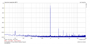
Just to make sure that the high order harmonics are really not the case of the measurement system, I made a comparative measurement at 20Vrms with another amplifier, with exactly same measurement system and settings as for A21 before. Both measurements shown.
Attachments

PMA, I do think that your measurement of the A21 is OK, BUT what about the bias setting?
Is it below 15mV? If it is, then rebias it. If it isn't below 15mV, then what do you suggest that I change to improve it? I do realize that the driver fets are somewhat underbiased compared to many other Parasound power amps that I have worked on.
Do you think that is the source of the VERY HIGH ORDER harmonics that you measured? That can be changed with a resistor value lowering.
Do you still have access to this A21? Perhaps I am asking too much. I would certainly like to fix the amp if I can. Perhaps I gave up on improving it prematurely.
It can be a warning sign, my neighbour collects green plastic milk bottle tops, "for no reason"Does it really matter what some people collect; wine corks, bottles, old HiFi, shoes, cars or even LP's.
The old legacy LP STILL does not sound as accurate as High Def 24/96+ wave files.
What do you use for a source?
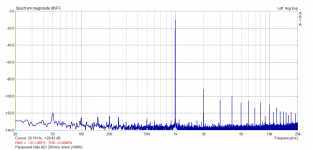
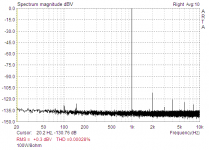
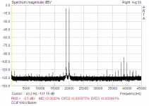
I have measured the signal source alone -
Attachments
PMA, I do think that your measurement of the A21 is OK, BUT what about the bias setting?
Is it below 15mV? If it is, then rebias it. If it isn't below 15mV, then what do you suggest that I change to improve it? I do realize that the driver fets are somewhat underbiased compared to many other Parasound power amps that I have worked on.
Do you think that is the source of the VERY HIGH ORDER harmonics that you measured? That can be changed with a resistor value lowering.
Do you still have access to this A21? Perhaps I am asking too much. I would certainly like to fix the amp if I can. Perhaps I gave up on improving it prematurely.
No, you are not asking too much. But, unfortunately, the A21 is not here in my lab now. It was here for just one day, last week, together with 2 other components of its owner. So, I am not able to answer your technical questions.
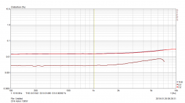
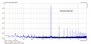
Though I cannot confirm or deny how big was the idle current, my suspicion is oriented to that measurement of THD vs. frequency. You could see that it was quite linearly rising with frequency. I suspect that feedback has not enough gain to reduce high order harmonics, seems to me that OLG corner is low, somewhere at 200Hz. Do you have an idea where it is?
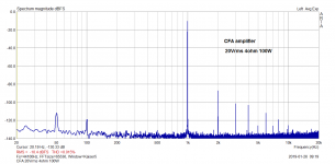
I have also measured, today, one of my older prototypes of the CFA amplifier. It has only a little more than 100W/4ohm maximum power. I measured it at 100W/4ohm, same as I did with A21, but for CFA, I was almost at the power limit. However, higher harmonics decay is faster, than for A21. Please also see THD vs. freq of that CFA, the plot is amost flat, OLG is quite high.
Attachments
Does it really matter what some people collect; wine corks, bottles, old HiFi, shoes, cars or even LP's.
The old legacy LP STILL does not sound as accurate as High Def 24/96+ wave files.
THx-RNMarsh
I would argue Jelly roll doesn't sound any better on 24/96!.
But you miss a gigantic point (because it doesn't matter to you). In terms an overall experience and satisfaction, especially when two are involved accuracy is not always the #1 priority. Case in point, last night we were listening to digital files off the server and, during a particularly good recording of the BBC SO I mentioned to my wife that I sometimes wonder why I play vinyl. She countered that digitial listening seemed impersonal in comparison.
So tonight with a glass of port we will listen to an LP and we will enjoy the experience.
So tonight with a glass of port we will listen to an LP and we will enjoy the experience.
We still have not opened my wife's birthday port, 1948 Taylor.
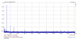
Years ago I simulated a very similar amplifier with the MOSFET drivers, like in A21. I was thinking about using the MOSFET drivers instead of 15030/31. But, the simulation result was full of high order harmonics, for higher power. Idle current is 85mA per pair, there are 4 pairs like in the A21. 19mV across one Re output stage resistor ......
Attachments
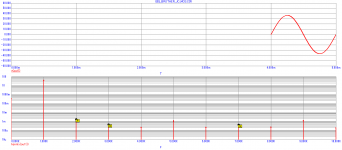
Idle current is 85mA per pair, there are 4 pairs like in the A21. 19mV across one Re output stage resistor ......
For the record I'm not a believer in these "optimum" bias points at all. For one thing they are very sensitive to temperature. IMO there is nothing like turning up the bias and using massive heat sinks, something like 500mA bias for a 100W/8 Ohm amp.
For the record I'm not a believer in these "optimum" bias points at all. For one thing they are very sensitive to temperature. IMO there is nothing like turning up the bias and using massive heat sinks, something like 500mA bias for a 100W/8 Ohm amp.
I have always used low bias currents, just enough to get rid of cross over distortion. Peavey do the same.
Any more current than you need just gets wasted as heat gets the amp nearer destruction temperature sooner.
I have always used low bias currents, just enough to get rid of cross over distortion.
I was referring somewhat to the mathematical argument that fails when the amp gets very hot, but yes in general I'm in The Son of Zen camp. Everyone carries on about the Otala amp and ignore the fact that he cranked the output bias up over the standard practice of the time.
We still have not opened my wife's birthday port, 1948 Taylor.
I had to do some mental maths there to be sure I understood what you meant there! I had a bottle of 63 Taylors on my 21st birthday and that was wonderous so I understand the fuss over really good port even if I can't justify it.
For the record that is the beauty of lateral mosfets .
The whole biasing thing takes care of itself .
I had a Maplin 75 watt lateral mosfet amp.
It always used to scare me as it ran so hot.
So i built up their 225WRMS bi-polar amp and that was great.
On my own designs the bias current is so small I can run at low volumes with no heat sink !
- Status
- Not open for further replies.
- Home
- Member Areas
- The Lounge
- John Curl's Blowtorch preamplifier part III