I'm needing to rework a flash system for a project I am working on and want to use a LED for a flash unit triggered by the hot shoe on a Nikon camera.
I understand most LED flash units use 3-5volts and I plan on using two AA batteries which will produce about 3v.
I also understand that the shoe is not a voltage supplier, but completes a circuit to ground allowing flash unit voltage to travel through the camera.
The 3v I intend to use will be no problem.
I am wondering if I need any circuitry at all? In other words, have the batteries connected to the led all the time and use the ground in the camera shoe to complete the circuit and fire the LED when I take a picture?
Am I thinking about this OK or am I missing something?
Last edited:
Being totally unfamiliar with any of this I'll throw a few thoughts into the ring......
You need to know whether the camera is a mechanical switch that closes or whether it is electronic (I would guess like an open collector type output).
If you only have 3 volts flying around then I can't see any problems on overvolting anything.
If the trigger is electronic then it may have significant internal resistance that could cause a problem if you try and switch a high current... and you do mention possibly switching the LED's directly. The camera switching may only be rated for milliamps at most. If the switch is mechanical then it will probably be a very small low inertia fast acting type and again not suited to high current.
Those are maybe just things to consider. Does that help") maybe not.
maybe not.
You need to know whether the camera is a mechanical switch that closes or whether it is electronic (I would guess like an open collector type output).
If you only have 3 volts flying around then I can't see any problems on overvolting anything.
If the trigger is electronic then it may have significant internal resistance that could cause a problem if you try and switch a high current... and you do mention possibly switching the LED's directly. The camera switching may only be rated for milliamps at most. If the switch is mechanical then it will probably be a very small low inertia fast acting type and again not suited to high current.
Those are maybe just things to consider. Does that help
maybe not.It's not quite that simple unfortunately. Led based flash units usually have a controller IC in them that generates a high current pulse to produce the flash. This will often be 400mA or more for a small number of ms. The LEDs used are designed specifically for flash applications. It's unlikely that a simple battery and switch will provide satisfactory results. You will probably fry the switch in the camera which I doubt is designed to handle more than a few mA of trigger current.
Here is an example of a circuit designed for camera flash applications.
http://www.ti.com/lit/an/slyt245/slyt245.pdf
A 3V power source such as a pair of AA batteries should work well in such an application.
Here is an example of a circuit designed for camera flash applications.
http://www.ti.com/lit/an/slyt245/slyt245.pdf
A 3V power source such as a pair of AA batteries should work well in such an application.
Led based flash units usually have a controller IC in them.....The LEDs used are designed specifically for flash applications.
As Kevin said both the driver circuit and the LED's are specially made for flash applications. I used to design cell phones for a living, and we used the special SMD flash LED's, but we used an I/O pin on the microcontroller to control them using PWM. A steady stream of narrow pulses in sync with the frame rate is used for video and one fat pulse is used for a camera flash. The newer phones have a flashlight mode which uses narrow pulses to avoid overheating the LED. The flash LED's have a high current chip or multiple low current chips inside, but they are not heat sinked sufficiently for continuous operation.
I make a piece of equipment that takes pictures of the iris for something called iridology.
Basically, I use a Nikon camera and 90m macro lens and some fiber optics that bring the light from the particular flash unit down the eye for good lighting.
I bought 100 flash units from China and guess what.... they break and no communication from the manufacturer.
Since I tooled up to use this unit, I am considering tearing out their electronics and Zenon tube and using a couple LEDs pointed at the two fiber optic cables to light the iris. The whole thing is running off the standard Nikon shoe using the center pin and ground.
It's a long way around, but I have a lot invested in the design surrounding the flash I have and this may be the best option.
It seems like a quick simple and cheap option?
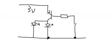
I was thinking something like this. The transistor should be a high gain type suitable for low loss switching. The resistor limits base/switch current. You may need limiting resistors for the LED's. LED's to be in parallel and not series as 3 volts is insufficient for series connection.
Attachments
I make a piece of equipment that takes pictures of the iris for something called iridology.
Basically, I use a Nikon camera and 90m macro lens and some fiber optics that bring the light from the particular flash unit down the eye for good lighting.
I can appreciate your wanting to re-purpose your LEDS but is there a reason for using LED flash?
Assuming your Nikon is APS-C, a 90mm macro lens at 1:2 magnification will give you a healthy distance between the lens and the eye for photography. Even at 1:1, there is still space.
The easiest and cheapest solution is mount two battery powered strobes on either side of the lens. Nowadays, they are pretty inexpensive.
An even cheaper solution is to use super bright LEDS and position them close to the eye. You should have more than enough lumens to shoot at 1/125 sec, f/11. Since they are continuous lights, you can see what you're shooting.
Something else to consider is the guidelines for eye safety with LED illumination, there is potential for retinal damage which is why the flash rather than continuous illumination may be safer.
Ensuring safety in LED lighting
Ensuring safety in LED lighting
This has been a learning process and I appreciate all that is being shared.
Thanks mooly for your diagram. It seems to me that something like this should be able to work. Am I wrong thinking the voltage switch can be the hot shoe completing the circuit?
I know in a standard flash design, the xenon flash units run 300v or more and the camera completes that circuit and the 300 plus volts runs through the camera.
I don't know enough to know if the two LEDS with 3v would in some way over power the camera capacity?
I also appreciate Kevinkr and your light spectrum and eye damage article. As it turns out, getting high-quality pictures take more light than what most people can tolerate with a constant light. Even with the camera set at ISO 800 and a wide open aperture.
A flash really is required for best pictures.
A xenon flash is almost constant across the whole spectrum from below 200nm all the way past 900nm so there is a LOT of energy in the 480nm range which would seem to make the xenon bulbs questionable with safety also.
It would be interesting for me to play with putting an absorptive film on the input of the fiber optics to reduce the 480nm spectrum and see how it affects the image quality.
Also, I've been looking at the PDF you sent. Thank you for that also. Do you see any challenges with moolies simple concept?
I really appreciate the input. Thanks
Thanks mooly for your diagram. It seems to me that something like this should be able to work. Am I wrong thinking the voltage switch can be the hot shoe completing the circuit?
I know in a standard flash design, the xenon flash units run 300v or more and the camera completes that circuit and the 300 plus volts runs through the camera.
I don't know enough to know if the two LEDS with 3v would in some way over power the camera capacity?
The LED's would be powered for as long as the switch contact was closed.
I have no idea what the duration of switch closure would be on a camera, however one possible option to give flexibility (if there were a problem) would be to use the switch to trigger a 'monostable' timer (such as CMOS 555 timer chip) and that would then generate a fixed duration pulse to illuminate the LEDs. The duration of the pulse is set by a single resistor which can be made variable.
The forward voltage of an LED (voltage needed for it to turn on and light) depends on the colour with red being the lowest at around 1.8 volts and white and blue the highest at anywhere between 3 to 3.8 volts. That is why you can not run them in series on 3 volts, there just isn't enough voltage available.
See reference 8.4.1 in the data sheet for the basic idea:
http://www.ti.com/lit/ds/symlink/lmc555.pdf
I've also no idea what the switch contacts are rated at in a typical camera but imagine it is not much current wise.
Xenon bulbs radiate well into the UV range which is not good for direct eye exposure.
Do not use the hot shoe to directly control the supply to the LED, I have built strobes in the past, and the hot shoe is designed as a low current switch. Direct switching of high current will destroy it.
Do not use the hot shoe to directly control the supply to the LED, I have built strobes in the past, and the hot shoe is designed as a low current switch. Direct switching of high current will destroy it.
> xenon bulbs questionable with safety
> Xenon bulbs radiate well into the UV range
These cameras route the flash through "optic fiber", presumably glass, low UV transmission, especially through several inches of the stuff.
And OP is planning to go LED, which I believe avoids UV output in favor of visible.
And light needed to take a clear picture on modern camera sensors is not large.
- Status
- This old topic is closed. If you want to reopen this topic, contact a moderator using the "Report Post" button.
- Home
- Member Areas
- The Lounge
- Anyone familiar with LED's for camera flash?