some smd advice ..
I hate the smd stripbooks, if you ever forget to slide the correct strip back in place you're hosed. so a measuring tweezer is a handy tool. I prefer the springloaded lid ESD boxes from
wolfgang warmbier. it's much faster to assemble something using these.
another one never place an smd resistor back into it's storage , drop it. blow it away, and take a new one that you are shure knowing it's value.
some smd advice ..never place an smd resistor back into it's storage , drop it. blow it away, and take a new one that you are shure knowing it's value.
I hadn't really thought much about that. I reworked that first mixer enough that I thought sure I would burn up a part, especially the JFET's. But they all survived.
On the other hand, I built a simple crystal controlled JFET Pierce oscillator next to the second mixer, worked great. Then I decided to "improve" it by moving it to another part of the board where I had more room for vcxo parts, a "better" doubler, etc., .... never could get the darn thing to oscillate again. It would draw current, but wouldn't do a darn thing. Still haven't figured out why.
I have some of the test tweezers - haven't used them yet.
Win W5JAG
with really nothing to show for it.
It's always a learning experience......even if it's learning what won't work.
I went to the Dayton hamfest and only brought back tubes, lots of tubes.
I went to the Butler Pennsylvania hamfest a couple of weeks ago and brought back about $150 worth of coax, antenna wire, and insulators. I also got two large Bud boxes and a Cushman CE-31 communications analyzer. One of the Bud boxes will be used for a remote antenna tuner.
......even if it's learning what won't work.
More and different from what I planned on or anticipated. As usual.
The current struggle is the second conversion, so why do I even need a second conversion?
These bags of microprocessor crystals are cheap. I'm wondering if an SSB bandwidth low VHF filter could not be made out of these crystals, and then the second conversion would not be needed at all. Out of a bag of twenty or more crystals, there should be four or six close enough in frequency to make a usable filter. MC1350 IF amp chips are intended for a low VHF IF, so an IF strip should not be a problem. The gain falls off some at VHF, so it might even be easier.
I think this FY6600 waveform generator can be made to sweep a range of frequencies within its limits, and the Hantek FFT may be able to show the basic response of a filter, at least the first 50 dB, so the skirts and ripple can be tweaked.
Is this too crazy?
Win W5JAG
to make xtal filters precise properties of the crystals are needed like motional inductance and capacitance and resistive losses. an AIM4170 or AIM4300 has an xtal measurement mode that can measure all these parameters.
not all xtals with the same freq are the same .
here is where you can find more about the filters:
Crystal ladder filter calculator
not all xtals with the same freq are the same .
here is where you can find more about the filters:
Crystal ladder filter calculator
Thanks for that link. Here is another one that I have found useful:
RF Tools - LeLeivre.com
I was thinking along the lines of a simple Cohn type filter. There is some information on these in January 1987 QST. The article is also reproduced at the back of W1FB's Design Notebook. That book can be downloaded at the link a few pages back.
Win W5JAG
RF Tools - LeLeivre.com
I was thinking along the lines of a simple Cohn type filter. There is some information on these in January 1987 QST. The article is also reproduced at the back of W1FB's Design Notebook. That book can be downloaded at the link a few pages back.
Win W5JAG
These bags of microprocessor crystals are cheap.......Is this too crazy?
I got a couple of big bags of crystals in the 15 to 20 MHz range with the idea of making a ladder filter narrow enough for CW (easier that an SSB filter). I lost my patience after playing for a couple of hours and haven't messed with it in a couple of years. I also have a network analyzer which makes things a bit easier.
.....even if it's learning what won't work.
This works.
Like it should.
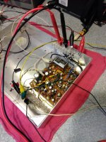
MW/ HF => 45 MHz => 9 MHz => FT-817. 36 MHz xtal 2nd LO, Si 5351 whatever using the FIXED LO as the TUNABLE LO.
IF I use this front end, I don't think I'll need an IF amp, but there is room allowed for one. If unneeded, I'll probably use that space to replace the 2 pole ECS filter with the 4 pole Tellurian.
The board works fine all the way down to 6 VDC.
The front end filter is just a test setup; it will probably become two bandpass filters, one for 20 meters, and another for 40.
The 2nd LO is actually going to go on the TX side; I want to add IF shift to the RX and this Pierce circuit doesn't lend itself well to a varicap type VCXO.
If this board doesn't make it into the actual radio, it will recycle as a single conversion BCB rcvr with a 45 MHz IF. Those narrowband FM filters work well for this.
Win W5JAG
Attachments
Yeah, thats what I thought.
Got an eBay account?
GSP Stole a very rare family heirloom from me toda... - The eBay Community
Got an eBay account?
GSP Stole a very rare family heirloom from me toda... - The eBay Community
Today's flash sale is 15% off everything.
Having played with it a bit, the double J310 JFET is definitely not a backwards move. I forgot to order any modern smd dual gate mosfet's, so I can't speak to them.
Now that the double conversion works like it should, one of the amusing things of playing around with this front end is the VLF performance of something with no filtering at VLF. My ham rigs are deaf below 500 KHz, but not this guy. This is the worst time of the year to listen, but I was tuning around the other evening and ran across one of the local non directional beacons at about 311 Khz, out in the Peno Bottoms, probably fifteen miles away. My "antenna" is the coax shield of the RG-59, feeding the test dipole that I use for the simple FM tuner built last summer, about twenty five feet in length, total. Not exactly resonant, and totally unmatched. I don't know the power of this NDB, but it uses an antenna not much bigger than mine, although I am sure it is matched, and it comes in at S9, with the FT817's RF amp off, and 20 dB of attenuation turned on. Prior to this, I had never heard one of these NDB's on anything but an ADF.
Win W5JAG
..... so I can't say whether this is better, worse, or just a sideways move from the usual dual gate MOSFET mixer
Having played with it a bit, the double J310 JFET is definitely not a backwards move. I forgot to order any modern smd dual gate mosfet's, so I can't speak to them.
Now that the double conversion works like it should, one of the amusing things of playing around with this front end is the VLF performance of something with no filtering at VLF. My ham rigs are deaf below 500 KHz, but not this guy. This is the worst time of the year to listen, but I was tuning around the other evening and ran across one of the local non directional beacons at about 311 Khz, out in the Peno Bottoms, probably fifteen miles away. My "antenna" is the coax shield of the RG-59, feeding the test dipole that I use for the simple FM tuner built last summer, about twenty five feet in length, total. Not exactly resonant, and totally unmatched. I don't know the power of this NDB, but it uses an antenna not much bigger than mine, although I am sure it is matched, and it comes in at S9, with the FT817's RF amp off, and 20 dB of attenuation turned on. Prior to this, I had never heard one of these NDB's on anything but an ADF.
Win W5JAG
Does it work?a Cushman CE-31 communications analyzer.
Mixers:
I have both a Crown FM1 & FM2. Both varactor tuned. They both overload.
The FM1 is 6 gang, 2 of 3n204 and a 2n5485 as the mixer.
The FM2 is 7 gang. It uses J310 as RF amps, mixer.
I found that a Sansui G-7500 with a bjt mixer seems to performs a bit better than the jfet mixers.
The Yamaha T-85 operates the best with its double balanced mixer using 2 of 3SK107(F).
a Cushman CE-31 communications analyzer......Does it work?
Yes, it does. I have not tested the absolute RF output level accuracy yet, but I have good signal generators for that.
We used CE-31's in the Motorola plant for final test and tune on the HT90 / HT440 products. I worked in the cal lab then and used to fix these things. It was cheap so I bought it.
I left the cal lab for an engineering job in 1984. We had state of the art HP stuff on our benches in engineering, but I always had a comm analyzer in my arsenal. It didn't get used often, but was a lifesaver when it did get used.
The most common use was to actually listen to your LO and reference oscillator signals to hear whatever crud was leaking into them. When we first started sticking microprocessors into radios (1979) such leaks were common, and hard to find. One of my first jobs in engineering was to hunt down a whining sound that would get transmitted if the radio was held just right. Everyone was focused on the microcontroller, but it turned out to be the multiplexing in the LCD chip. A little patch of copper tape in the right place......and all is well.
As with w5jag's FT-817, it can be used as a radio back end for testing, although I also have an 817.
We had this conversation before.
I remember a older Cushman model(CE-3) with the scope. There was the Motorola model as well. Used mainly for the field. The factory in Toronto switched over to using Boonton mod analyzers and some HP 8901A, 435 or 436 power meter, 8656B RFSG's mostly. I have the same setup in my lab here at home. 8901A's go for $100 on a good day, 8656B a bit more.
Trivia, the 8656B I have is from an EE that bought it at the Motorola auction when they shut it down the labs here in Canada. I might have cal'd it one day at work and did not know I would own it one day.")
Wish I had a RF spectrum analyzer/tracker to play with but they are still pretty pricey and hard to justify in my mind such an expensive toy to play with.
Also remember the Wiltron sweeper/ return-loss bridge setup to tune the RF FE's on the MCX100, slick. The EE had a patent on the helical tuned filter design I was told.
That Cushman CE-50A looks pretty cool.
I remember a older Cushman model(CE-3) with the scope. There was the Motorola model as well. Used mainly for the field. The factory in Toronto switched over to using Boonton mod analyzers and some HP 8901A, 435 or 436 power meter, 8656B RFSG's mostly. I have the same setup in my lab here at home. 8901A's go for $100 on a good day, 8656B a bit more.
Trivia, the 8656B I have is from an EE that bought it at the Motorola auction when they shut it down the labs here in Canada. I might have cal'd it one day at work and did not know I would own it one day.
Wish I had a RF spectrum analyzer/tracker to play with but they are still pretty pricey and hard to justify in my mind such an expensive toy to play with.
Also remember the Wiltron sweeper/ return-loss bridge setup to tune the RF FE's on the MCX100, slick. The EE had a patent on the helical tuned filter design I was told.
That Cushman CE-50A looks pretty cool.
Last edited:
It occurs to me that if the tunable LO stays put, and with a fixed BFO frequency, then moving the second LO back and forth across the IF implements the IF shift feature of low end transceivers?
even if it's learning what won't work.
Yeah, that won't work. Moving the second LO just changes the pitch.
I put the second LO on the board next to the second mixer; the 54 MHz crystals are way overdue, so I am using 36 MHz at present. I've decided to make a new BFO board using the LM375 to inject carrier into the Mizhuo SG-9, so 36 MHz or 54 MHz, not really a big deal other than sideband inversion ( or not ), unless there is some other reason to choose one frequency over the other that I am not aware of.
This seems to work pretty well. It puts out about 6 v P-P, with very little second harmonic according to the Hantek FFT. One of the things I've noticed about using two JFET's to emulate a dual gate MOSFET device, is that the dual JFET combination can eat LO voltages that would likely kill a 40673 on the spot. The JFET x 2 mixer seems to be able to get down to background noise with just the LO voltages typically used with dual gate MOSFET's, but I expect strong signal handling would be better with higher LO voltages.
I didn't have much luck using the J310 as an oscillator. Well, actually, I did, but all of it was bad. They would run for a bit, and then die. I lost two J310's this way, gave up, and just moved on to using an obsolete MPF102, which works fine at 36 Mhz, and should be fine at 54 MHz.
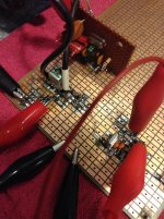
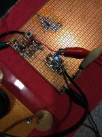
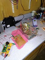
I would like to say that the cheap cell phone picture is not an accurate representation, and that the board looks better in real life, but it doesn't. It is gouge your eyes out ugly - just a mass of black and white blobs, stale solder, and copper pads. I put that little LED in just to add some color and amusement.
The SMD thing is a bit harder than I anticipated, but I think I am starting to see how to better exploit it, and better utilize this prototype board. The good thing is that it works a lot better than it looks. It seems to work exactly like one would expect it to.
I'm pretty far behind on mowing, and the next bit of time I have will be spent going up to Grand Lake ( near Tulsa ) to mow a lot I have up there, and then I have several more closer in I need to get done, as well as the second house up at the lake, so I will have lots of time to think on this.
Win W5JAG
Attachments
I think this is the longest I've ever spent on an uninterrupted single project, with really nothing to show for it.
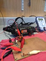
So, a YEAR in, just to have something to show for it, I decided to start piecing it together as a radio to see where I was at, or if I should just toss in the towel .....
I put the SG-9 in the box, and brought all the i/o out to barrier strips for testing. I have it hardwired for SSB; it still takes about 24 connections to get to everything even without mode switching.
The electrolytic caps are about four decades old; on a case by case basis I may replace some of them, it's not a high priority right now.
My goals are always pretty simple:
1) I can actually make it work ( sort of );
2) it won't drift ( a whole lot );
3) I can actually make QSO's with it, or listen to it all day without having the urge to drive a nail through my ears.
The up conversion to low VHF, and tossing SMD in on top of that, may be a deviation away from simple. I don't really know - simple is a relative thing, I guess. Having gotten the Si5351 whatever figured out, It doesn't just sort of work, I think it is going to work pretty well.
With two crystal oscillators and a synthesizer, it does not drift a bit, even with an air conditioner blowing across it.
No TX, so, no QSO's yet, but it sounds good. I was a bit taken aback at how good it sounds into a full range speaker.
Sensitivity: I'm not sure. I think it may be OK.
When I had everything hooked up, ( using the coax shield as an unmatched random length antenna ) I brought it up on the broadcast band and was disappointed. Sensitivity seemed doggish. I started tuning up the HF band, and it seemed better. Better than when the FT-817 was the back end.
The low end of 40 meters was absolutely jam packed full of CW signals for the contest last night, and it sure did not seem to lack any sensitivity there. I was really a bit surprised at how good it sounded - I listened for a couple of hours to CW. With a wide passband ( I think it is 2.5 KHz, and only six poles ) the audio quality was so clear I had no difficulty picking a single signal out of the passband and focusing in on it, to copy it in my head. The longer I listened to it, the better I liked it. It just seemed to get better the longer it ran - perhaps the old electrolytics in the SG-9 were reforming.
So, for now, I feel a bit better about the project.I 'm going to start looking for a case to make a control head for the radio.
Subject to a little more playing around with it, I think I am going to stick with the unbalanced dual JFET's as the front end. I didn't notice any overload on 40 meters, and it's getting more signal with the wire than it will with a mobile antenna. I didn't notice any FM or MW breakthrough, but I wasn't really looking for any, yet. I haven't tried sideband, because they are flipped. AM SW stations come through just fine on one sideband.
The little meter off to the side was to monitor the AGC line and "S" meter output. Both seem to work properly.
Win W5JAG
Attachments
- Home
- Member Areas
- The Lounge
- No RF gear here?