I'm going to have some LC circuits that I have no realistic way to accurately measure or characterize, so I thought I would try to select components as close to the calculated values as reasonably practicable, as a substitute.
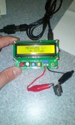
I got an LC-100-A LC "meter" that has been on the market for a few years now from $13-25, or so, depending mostly on how fast you want it. I had been using a dip meter, but it is tedious, and ball park accurate at best. This gives only inductance, no other parameters, but for $20 ish, it's a bargain, I think.
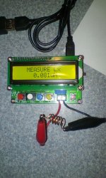
Once calibrated ( easy ) this thing will measure a sack of coils faster than Jack can jump over a candlestick. It looks to be useful for all RF type coils. Pics are shown measuring a typical small value slug tuned inductor, and an air coil. I have not used it for C, yet.
I should have semi suitable coils in my parts inventory ( may not be shielded, though ), so, next stop, solder.
Win W5JAG
edit: one other question: the main RF unit is planned to be in the trunk. In Arkansas, the temperatures can be extreme - below 0 F in Winter, and well past 100 F in Summer, with almost 100 % humidity. I think can make most of these small value inductances as air coils. Would that be preferable from a temp stability standpoint, as opposed to a slug tuned coil?
I got an LC-100-A LC "meter" that has been on the market for a few years now from $13-25, or so, depending mostly on how fast you want it. I had been using a dip meter, but it is tedious, and ball park accurate at best. This gives only inductance, no other parameters, but for $20 ish, it's a bargain, I think.
Once calibrated ( easy ) this thing will measure a sack of coils faster than Jack can jump over a candlestick. It looks to be useful for all RF type coils. Pics are shown measuring a typical small value slug tuned inductor, and an air coil. I have not used it for C, yet.
I should have semi suitable coils in my parts inventory ( may not be shielded, though ), so, next stop, solder.
Win W5JAG
edit: one other question: the main RF unit is planned to be in the trunk. In Arkansas, the temperatures can be extreme - below 0 F in Winter, and well past 100 F in Summer, with almost 100 % humidity. I think can make most of these small value inductances as air coils. Would that be preferable from a temp stability standpoint, as opposed to a slug tuned coil?
Attachments
Last edited:
I had been wondering where the Tellurian filters were - had to go back home for a few days last week and found them in an envelope in a stack of junk mail. Mine came with gold plated leads.
I found a few MMIC's in my junkbox - NEC upc1651G, a 5 volt part, but looks ok otherwise; about 5 dB NF and 19 dB gain at HF. The sheet I have says nothing about matching in / out. Looks like it's a 1983 ish device. No apparent way to apply AGC.
What do you guys think of these modern IC mixers, like this AD831 example:
AD831 high frequency RF mixer drive Amplifier Module HF VHF/UHF 0.1- 500MHz | eBay
Pretty high Ip, but seems noisy from looking at the datasheet, not sure that would matter much at HF. A little less cost than an SBL-1 and if I am looking at the sheet right, matching in / out is not especially critical.
The Analog Devices eval board is over $100 at DigiKey, so these boards seem like a deal. I would remove the sma connectors.
Still on mostly holiday staycation at the lake, so, no hardware progress on any project.
Win W5JAG
... Mini circuits do some great broadband MMICs which are 50 ohm input, or very easy to match to that...
I found a few MMIC's in my junkbox - NEC upc1651G, a 5 volt part, but looks ok otherwise; about 5 dB NF and 19 dB gain at HF. The sheet I have says nothing about matching in / out. Looks like it's a 1983 ish device. No apparent way to apply AGC.
What do you guys think of these modern IC mixers, like this AD831 example:
AD831 high frequency RF mixer drive Amplifier Module HF VHF/UHF 0.1- 500MHz | eBay
Pretty high Ip, but seems noisy from looking at the datasheet, not sure that would matter much at HF. A little less cost than an SBL-1 and if I am looking at the sheet right, matching in / out is not especially critical.
The Analog Devices eval board is over $100 at DigiKey, so these boards seem like a deal. I would remove the sma connectors.
Still on mostly holiday staycation at the lake, so, no hardware progress on any project.
Win W5JAG
Last edited:
I have no experience with these; Gilbert cells are not praised for
their dynamic range. But it is a cheap test and easy to get something
running in the first place; optimizing can be done later if needed.
I have ordered a RedPitaya yesterday; that should take care of
the basic RX & TX from DC to 60 MHz, and it also can be used
as a simple scope, spectrum analyzer and signal generator.
A lot of value for €310.
I'll then build transverters for 144 (adding 100 MHz) and for
432 (adding 2*2*100MHz). The userinterface/firmware will
be HPSDR, someone has done that already. Thus the
total effort shrinks to sth. that can be done in finite time.
BTW for the inductance measurements above, one cannot
ignore the cables with the gator clips. That must be minimized.
73, Gerhard
< SDR transceiver compatible with HPSDR >
...for the inductance measurements above, one cannot ignore the cables with the gator clips. That must be minimized.
It zero's out, more or less, in calibration. Cross checking it by measuring marked coils, it seems to read those correctly, or at least within their stated tolerance.
I haven't ordered any of those mixer boards, yet, and may not. They might make an interesting front end for a direct conversion receiver or maybe a product detector. They claim +24 dBm intercept with very little LO drive required, and no or negligible conversion loss.
Win W5JAG
I've got the RedPitaya today. It is not much bigger than a credit card.
Gets quite hot & will definitely need a fan. I can see it on the lan and
ping it, but I have not been able to install some SDR software that
can use it.
BTW one interesting RX website (switch mixers etc) :
< H-Mode mixer >
Cheers, Gerhard
Gets quite hot & will definitely need a fan. I can see it on the lan and
ping it, but I have not been able to install some SDR software that
can use it.
BTW one interesting RX website (switch mixers etc) :
< H-Mode mixer >
Cheers, Gerhard
I guess this is what happens when you lose interest and let your subscriptions to periodicals lapse.
Like Tayloe demodulation, I have not heard of "H Mode" mixing before - it looks to be a variant of, or the name designation for, switches used as mixers?
Looking into it a bit, I found this page: 2.3 H-Mode-Mixer which apparently references this diy board:
FSA3157 H-Mode RF Mixer Module | eBay
Win W5JAG
....I have ordered a RedPitaya yesterday; that should take care of
the basic RX & TX from DC to 60 MHz, ....I'll then build transverters for 144 (adding 100 MHz) and for 432 (adding 2*2*100MHz). ....
This guy: Red Pitaya ?
Win W5JAG
Exactly that. I think it is available at Digikey, also.
I'm just trying the apps that are are delivered with it.
There is a signal generator, scope, FFT analyzer and
also a SDR, an implementation of HPSDR for it.
Currently, I'm a victim of the fact that I have spent much
effort to carefully hide my Windows virtual machines to
the network.
cheers, Gerhard, dk4xp
Attachments
Last edited:
I wrote ping 192,168.178.61 Windows ping did not complain and pretended
that no other device in my LAN was visible.
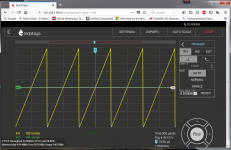
The SDR software still does not work, but the scope function does:
500 mV sawtooth from my HP3325B without the 50 Ohm load, so 1Vpp
is correct.
The scope function seems to access a web site in the Pitaya via firefox.
WOW, 14 bit 60 MHz scope!
At least the networking must be ok now.
that no other device in my LAN was visible.
The SDR software still does not work, but the scope function does:
500 mV sawtooth from my HP3325B without the 50 Ohm load, so 1Vpp
is correct.
The scope function seems to access a web site in the Pitaya via firefox.
WOW, 14 bit 60 MHz scope!
At least the networking must be ok now.
Attachments
Last edited:
So how is the Red Pitaya working?
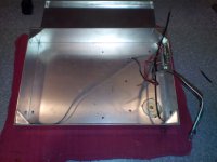
I finally got to burn a little solder on this project. It's been brutal cold here, and my ham shack is deeply cold soaked - like being in a meat freezer, so two or three hours was about all I could stand this afternoon ....
This board will be to convert the final IF ( whatever that turns out to be ) to 14 MHz via 45 MHz. TX on one side, RX on the other, T/R switching and misc. stuff in the middle. I put a relay in for antenna switching, for now. Not sure yet how I'll switch the LO's, or even if they need to be switched ....
I'm going to use the small aluminum box for the RF chassis, it's about 9 x 7 inches, so should be adequate. The xmtr pa will mount on the outside surface. This chassis is from an early crystal controlled, trunk mount / control head, 2 M FM radio I built, so won't need a lot of metal work.
Hopefully tomorrow I can finish out the front end, and test it for IF output at 45 MHz.
Win W5JAG
Attachments
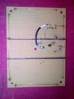
Modest success!
I didn't like where the IF port wound up, so I reoriented the mixer can.
I hooked up a two element beam to the RF input, the DDS to the LO port, and took the IF through a 0.01 uF disc direct to the #2 antenna input on an HF rig.
The background noise came up, and with a bit of diddling, got the Collins net on 14.263 MHz, even though band conditions are LOUSY here ....
The DDS needs to be calibrated - it's about 1.5 kc off. The sidebands are inverted - the rcvr is tuned to 45.000.00 LSB to get the net.
Not sure if I will stick with the SBL-1 or not, but, it's converting HF to 45 MHz .....
Win W5JAG
Attachments
Used to have some Cobra 148 GTL-DX during the early '80 though to late 80's when I packed it in around '88?
Had a few base station antennas GPA 1/2 wave and three element beam with 1/4 wave, high gain CLR II, comtell 444 30 footer and Astroplane. Big Mama mobile and DV27 on a biscuit tin.
During using the high-gain CLR-II and burner with a rather one day, odd SWR that didn't look good on some of the low bands at near RED, BAD! Mild midway reading though mid and high bands. Also changes slightly when using any one of the 5 modes CW, FM, AM and SSB single side bands USB, LSB (upper/lower).
Not aware I had a lose dry joint on the coaxial centre core of the cable output of burner to Ant.
It played havoc with TV and VCR in the lounge with VCR going into visual fast speed mode when TX transmitting. When using the remote I got something like x10 times speed which was unheard of a VCR at the time. It sort of shorted out the TV after few minutes of transmitting!
Push switch in and pull out TV came back on so knowing today it had a sort of fail-safe maybe like for lighting strikes or power spikes?
However for my dads friend neighbor some 5 doors along some 200 feet or so distance away it wasn't good for his Sony TV. Seems like 200watts blew his TV set-up!
Yes he was red face when he came ranting in the home telling me I killed his TV set.
So few days after I checked the coaxial and re-soldered it. I should have checked the coaxial first time I noticed the dodgy looking SWR.
I have no idea what the signal wave form would have looked like to blow up a TV set what ever it must have been a demon RF signal from hell.
I mean what are the odds of that happening? Sure TVI was common thing but blowing a TV set?
Had a few base station antennas GPA 1/2 wave and three element beam with 1/4 wave, high gain CLR II, comtell 444 30 footer and Astroplane. Big Mama mobile and DV27 on a biscuit tin.
During using the high-gain CLR-II and burner with a rather one day, odd SWR that didn't look good on some of the low bands at near RED, BAD! Mild midway reading though mid and high bands. Also changes slightly when using any one of the 5 modes CW, FM, AM and SSB single side bands USB, LSB (upper/lower).
Not aware I had a lose dry joint on the coaxial centre core of the cable output of burner to Ant.
It played havoc with TV and VCR in the lounge with VCR going into visual fast speed mode when TX transmitting. When using the remote I got something like x10 times speed which was unheard of a VCR at the time.
It sort of shorted out the TV after few minutes of transmitting! Push switch in and pull out TV came back on so knowing today it had a sort of fail-safe maybe like for lighting strikes or power spikes?
However for my dads friend neighbor some 5 doors along some 200 feet or so distance away it wasn't good for his Sony TV. Seems like 200watts blew his TV set-up!
Yes he was
red face when he came ranting in the home telling me I killed his TV set. So few days after I checked the coaxial and re-soldered it. I should have checked the coaxial first time I noticed the dodgy looking SWR.
I have no idea what the signal wave form would have looked like to blow up a TV set what ever it must have been a demon RF signal from hell.
I mean what are the odds of that happening? Sure TVI was common thing but blowing a TV set?
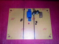
Modest progress.
A somewhat better front end. 5 pole high pass filter, feeding a three pole low pass filter, then into the RF port, basically bracketing the HF band 3 - 30MHz. The BCB interference plaquing the test setup is resolved. Tunable coils seemed goofy, since I have no means of sweeping them, so have been replaced with fixed inductors.
Less sensitive than I would like. The Rube Golderg attenuator on the DDS needs to go. I'm sure I'm losing signal taking the output through clip leads.
Still not sure I want to use a passive mixer. Listening to W1AW on 20m CW right now.
Win W5JAG
Attachments

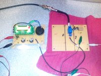
Tuning around in the general coverage parts of HF, I found some FM BCB breakthrough. I just assumed it was coming on the antenna, since I didn't have much low pass filtering, so I reworked the hi pass filter to five poles, which didn't help.
The worst offender is a 100KW rig about 11 miles north of me, LOS.
The front end is solid, it's not coming in on the antenna, since it's there with the antenna disconnected .... I got rid of all the clip leads, and that didn't make any difference. It appears to be being picked up in the board itself, possibly on the power leads going to the DDS.
None of the breakthrough is in a ham band, or what's left of the SWL bands, so not a big deal, I guess, but it still bugs me. Hopefully it will resolve when everything is in a metal chassis.
Anyway, while fiddling around with this, I listened to a few SSB traffic nets on 75 meters, and did some swling. I got rid of the "attenuators" on the DDS board, and that helped quite a bit, getting a better LO drive into the mixer.
Win W5JAG
Thanks guys for the fresh air you bring here 
These, in case of TX activities
https://www.ntia.doc.gov/files/ntia/publications/january_2016_spectrum_wall_chart.pdf
Download the European Frequency Allocation Charts. | Electronic Design
http://www.erodocdb.dk/docs/doc98/official/pdf/ercrep025.pdf
http://www.erodocdb.dk/Docs/doc98/official/pdf/REC7401E.PDF
http://www.erodocdb.dk/Docs/doc98/official/pdf/REC1203.PDF
George
Thanks guys for the fresh air you bring here
These, in case of TX activities
Looks like intentional TX is still a ways off .....
I think the DBM ( LO - RF isolation should be about 55-60 dB down at these frequencies ) and low pass filtering is keeping whatever is going back out the antenna legal. If I change IF's, I'll have to take another look at that ...Fooling around with this some more, I decided to change the IF frequency to 10.7 MHz, hi side LO injection, just for a look see. To eliminate antenna selectivity as a variable, I hooked up a random wire, 25 or 30 feet, or so, as an antenna. I ran the DDS off a battery, to eliminate trash from the power supply as a possible cause.
I only checked below 15 MHz, but all of the FM BCB artifacts look to be gone ..... The noise floor came down, a lot, and sensitivity was about what I would expect for this type of front end. Everything worked as one would expect.
The front end filtering, the hi pass part, anyway, works. I tuned to a local MW station at 1.32 MHz, and going through the hi pass filter, it was about S-5. Hooking the random wire to the low pass section, bypassing the hi pass, it went to 30 dB over S-9. So, while not calibrated, clearly it has significant attenuation as planned. Haven't checked the low pass part, takes a long time to spin the DDS up there, but I have no reason at this point to think it is not working as planned.
So, looking to be some kind of odd artifact of these parts associated with the 45 MHz IF. Has anyone seen a rig that uses this cheap SI DDS chip with a low VHF IF? Thinking about it, I have not. The ones I have seen are all using it at around a 9 MHz IF .....
Might try filtering the DDS LO to see if that helps. It may just be unsuitable for a 45 MHz IF
.Win W5JAG
Did the FM interference appear on some discrete frequencies? It may be a typical response, or an image response created by a harmonic of the DDS output mixing with the FM BCB's frequency to make 45MHz.
If you can find one of the spurious responses post it's frequency and the frequency the DDS is set to, and maybe we can figure out how it happens.
it is also possible that you have found a spurious artifact from the DDS chip itself. Many of them create internal spurs due to the interaction between the clock and sampling freq. Which DDS chip are you using?
Sort of.
I didn't take notes, but it's every couple of MHz, and a real high noise floor everywhere else, that I really didn't notice until I changed the IF. I just thought the sensitivity sucked. It comes through as a strong broadband signal, about 150 - 175 KHz wide ( FM channel width ), and it took me a little bit to figure out it was FM BCB coming through. Once I decided it was FM interference, I listened to it for modulation artifacts using slope detection, and was able to match it to a station at 95.7 MHz.
So, knee jerk reaction, I just assumed it was getting through the front end as a mixing product, and increased the low pass filtering. I'm using a Chebyshev (sp?) five pole filter, LCLCL, with a cut off at 30 MHz, FM band should be at least 35-40 dB down.
But it's not coming through the front end. It's there with no antenna, all cables shielded at one or both ends. The worst offender is that 100 KW station at 93.7 Mhz, but others are coming through as well.
The DDS chip is the Si5351. I'm only using one output at the moment.
Win W5JAG
.... or an image response created by a harmonic of the DDS output mixing with the FM BCB's frequency to make 45MHz. ....
This is just one frequency example I can specifically recall. Someone check my arithmetic, please.
There is a local BCB station at 1.23 MHz, that is totally unreceivable with the 45 MHz IF. It’s just a broad bunch of cross mod garbage. Sounds terrific with a 10.7 MHz IF, if I bypass the hi pass filter.
46.23 MHz hi side LO minus 45 MHz IF = 1.23 MHz
I noted in post #119 the third harmonic was "horrendous". (46.23 LO) (3) = bonus 138.69 MHz LO, probably as strong, or stronger, than the fundamental.
138.69 MHz hi side LO - 45 MHz IF = 93.69 MHz.
100 KW station at 93.7 MHz.
I bet if I took the time, I could do the math on all of them.
Filter the LO?
Win W5JAG
- Home
- Member Areas
- The Lounge
- No RF gear here?