... A square wave by definition contains ALL of the odd order harmonics. ...
I did expect this to be a learning curve. I just didn't expect the learning curve to be so abrupt. I've barely put solder to the iron, at this point ....
... Many of the typical diode or fet ring mixers actually work better when the LO port is driven by a square wave ...
I had planned on doubly balanced active mixers, because I want the conversion gain. But the square wave situation has made me think more about that per your earlier comments.
Besides the signal handling, I see real practical benefits to using some mini circuits mixers: easier ( probably ) to build, 50 ohm ports, pre fab construction, small size. Gain / loss isn't that big a deal, I guess, one chip or transistor can make that back up.
If I use a pre fab diode ring, then I can just try using the DDS output as is?
I thought I would play some with low pass filtering it, just to see how much I can clean the output up, and maybe get something closer to a sine wave.
Also, you or Gerhard mentioned quad FET switches, I think, as mixers. I ran across about a dozen 4064, or something like that, while I was looking for mixer chips. I have no idea what I originally bought those for ....
Win W5JAG
I ran across about a dozen 4064
4016 maybe? It's a quad analog switch, and you can make a switch mixer out of it. There are better chips these days but many of the really good ones are only made in SMD. The key specs are low on resistance, high isolation at the frequency of use when off, and low channel to channel leakage. Basically you wire a switch in place of each diode in a ring type mixer, and switch them with the LO signal.
Look at the schematic for the Soft Rock 9.0 SDR.
Lite + Xtall RX V9.0 - Schematic
Here the antenna (or IF signal) in light blue lower left, is applied to two pairs of inputs on a multiplexer chip (pre wired and decoded analog switches) through a pair of 10 ohm resistors (brown section). The LO is generated in a Silicon Labs chip similar to your Russian kit (orange), and then run through a divide by two (blue) to make a pair of LO signals that are 90 degrees out of phase and 50 - 50 duty cycle, then applied to pins 2 and 14 of the multiplexer (mixer) chip. In this radio the "IF" is a low frequency signal that covers a few KHz up to 50 to 100 KHz which is amplified (grey) and sent to the sound card in a PC which acts as a DSP. You could run this at 455 KHz with appropriate opamps and reducing the value of C26 and C27 by a factor of 10 or so.
This type of radio needs two IF signals known as I and Q for accurate demodulation in a DSP (quadrature demodulation). You do not need two different IF signals, so half of this circuit is not needed.
This type of design was invented by a field service technician and ham radio operator who worked at Motorola (the Tayloe demodulator). It was first used in the original Flex 1000 from Flex radio systems. We still use this technology today in the ultra high end APX7000 police radios, although it is all integrated into a custom RF IC.
My bad, they are CD4066, with 1983 date codes, so I've had them a while. One even has RCA marks.
I guess I could use them as audio switches in that preamp/audio switch I'm supposed to be building as a companion to that simple FM stereo tuner. I was planning on using LM1037 since I have a few,with a one shot to toggle the inputs, but CD4016 or 4066 would be more reproducible on the off chance someone wanted to build a duplicate.
I *think* I get the gist of that mixer in the soft rock - the bifilar transformer on the input is making two out of phase signals to the rf input on the switch chip; the 7474 is making the equivalent of two out of phase signals off the DDS to the LO side of the switch; and then the output at RF would be taken through another bifilar transformer to recombine the IF, or just take one output single ended, and ground the other at RF through a cap? That floating antenna input seems weird, though.
I presume, then, this is a unity gain mixer as opposed to the 5 or 6 dB loss through a diode ring?
That QRP Labs bunch look like they have really exploited the Si5351 chip to a high degree. If I was reading their literature correctly, their firmware exploits the outputs on the chip to produce the quadrature output for Tayloe demodulation, which I confess I had not heard of before yesterday, so their DDS looks to be well suited right off the soldering iron for SDR.
I had hoped to already have a working 45 MHz If at this point; I hadn't planned on getting schooled in DDS even at this superficial level, but that's OK I guess - it's the 21st century and I might as well be dragged kicking and screaming into it .....
Win W5JAG
Ham radio today is incredibly inexpensive and easy to get into. I can give you two cheap, and highly gratifying pointers. We're talking under $200 to get into a lot of fun.
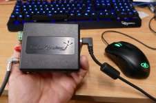
One, an SDR receiver product out of the UK: SDRplay
That, in combination with any number of simple homegrown receive antenna will get your receiving anything from "DC to Daylight" lol.
Two, a QRP Beacon and 24x7 sighting network based on the WSPR modulation scheme. QRP Labs Kits
Using the inexpensive qrp labs kit, you can setup a GPS synchronized transmitter and get your tranmissions observed half-way across the world using the WSPRnet reporting network. Built one of these, and I run one occasionally in my kitchen - with a loop antenna aimed out the Window, and get heard from Boston to Belgium or Boston to the UK on under 1 W of transmit power. You do need a General license though to transmit - so please study and take those tests before your power one of these 1 W or 2 W beauties up.
These are just two examples of projects similar in popularity to some DIY audio projects (i.e. tubelab, aikido, passlabs, bottle head, etc)
-- Jim (AB1RW)
We're talking under $200 to get into a lot of fun......One, an SDR receiver product out of the UK: SDRplay
I got one of those. I have tested it in my FR black hole, underground in the basement of a house which is in a "holler" surrounded on all sides by tall (100+ feet) hills. We get no cellular or TV reception here and little broadcast radio. I also purchased a "broadband ham and scanner antenna" on Ebay, but haven't had the time to put it up yet. When I do, I will also put up some sort of HF antenna. I had a "Mystery Antenna" up in Florida, but it picked up more noise from the nearby EHV power transmission lines than it did radio signals.
With the crude underground setup I don't have many signals, and I have a lot of random RF from the PC, it's displays (cheap TV sets), and the Comcast Box. All of these are within 3 feet of the clip lead antenna.
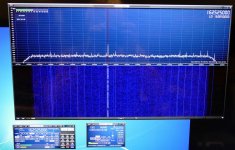
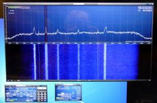
The SDR Play can be set to "swallow" as much as 10 MHz of spectrum at a time, and display it spectrum analyzer style, with a waterfall histogram below. Shown here is the local weather broadcast on 162.525 Mhz in a 2 MHz capture window. It is telling me (through the PC speakers) about the snow that we are going to get Saturday night.
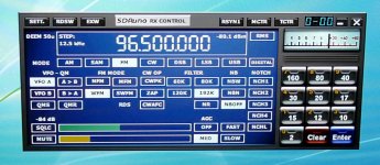
I also grabbed a 10 MHz chunk of the FM broadcast band, and tuned in the local rock station on 96.5 MHz.
Also shown is the RX control panel. Here you can choose the IF filter, FM mode (wide for broadcast radio, narrow for ham FM), noise blanker and notch filter for removing a pesky signal.
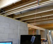
When I can get my laptop working, I want to take this setup to a location I call "on top of the world." It's about 400 feet above the town and even with the surrounding hills. The county wide public safety tower is up there though. We should see how well this thing rejects strong signals a few MHz away.
You do need a General license though to transmit
My call (KB4LRE) may be an old novice call, but I upgraded to extra some time ago. I kept the old (randomly assigned) call sign since my favorite childhood hangout was the Lafayette Radio Electronics store in South Miami.
My bad, they are CD4066
They could be used as a mixer, but would be lossy with a 125 ohm ON resistance in a 50 ohm system. There are 5 ohm chips out there today. The chips that I had chosen for a mixer several years ago are the TI SN74CBT3253 (7 ohms) or the Fairchild FSAV332 (3 ohms). The TI lists a DIP part but Mouser doesn't have them. The Fairchild part is only SMD, but goes beyond 300 MHz.
I presume, then, this is a unity gain mixer as opposed to the 5 or 6 dB loss through a diode ring?
This type of mixer will still have some loss due to the los through the baluns, and switches, but it should be lower than a diode ring. We were getting about 4 db loss at 850 MHz converting down to 109.65 MHz, the ring was about 8 db.
RF would be taken through another bifilar transformer to recombine the IF, or just take one output single ended
It is not quite that simple since the Mixer shown is making quadrature outputs (90 degrees out of phase). You just can't combine them in a balun. One output can be discarded, but there is a better way. I need to dig through my old schematics. I did have a complete IF backend breadboarded somewhere. The system used in the Soft Rock is a quadrature SAMPLING DEMODULATOR, it has a low pass response built in due to the sampling cap and resistive losses. This is a useful feature for the intended application, and also somewhat useful when used as a mixer, but some changes were required.
Attachments

They could be used as a mixer, but would be lossy with a 125 ohm ON resistance in a 50 ohm system. There are 5 ohm chips out there today. The chips that I had chosen for a mixer several years ago are the TI SN74CBT3253 (7 ohms) or the Fairchild FSAV332 (3 ohms). The TI lists a DIP part but Mouser doesn't have them. The Fairchild part is only SMD, but goes beyond 300 MHz.
Right now on my table, there are some NLAS4684NR2 (On Semi, also Maxim)
that feature 500 mOhm. Tiny MSOP-10, but all the interesting newfangled stuff
is that small nowadays. There is something similar from AD in sot23-6.
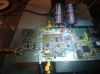
I'm trying to build a chopper amplifier at 100 pV/rt Hz that upconverts to 1 MHz,
amplifies and downconverts again with the FET switches. Transformers are
small MACOM and Pulse engineering thingies, I had to rewind some of them ,
3 mH for 32 turns. Had to solder them to a breadbord and then wind them under
the microscope.
")
I want to get rid of the 1/f noise.
The CPLD allows me to alingn the up- and down conversion switches to make
up for the amplifier delays. The oscillator is 100 MHz, that allows 5 nsec of
resolution, which is probably much better than needed.
I get terrible switching glitches, some of them 2 nsec wide.
This is Version 2.5, with a lot of rucksacks for the changes, but it starts
to converge.
Last edited:
there are some NLAS4684NR2
It seems that the number is NLAS4684MR2, at least that's what Mouser has for the MSOP part. They are the lowest ON resistance parts I have seen, especially on a 5 volt supply, but they aren't fast enough for use as an RF mixer in a radio application. You have reminded me that it's been several years since I have even looked into parts for an RF project. I'm sure that there is all sorts of new stuff out there that I don't know about, and a few that I have known and used, that no longer exist.
all the interesting newfangled stuff is that small nowadays.
I think we (Motorola) were part of the force that drove that trend. I asked why we were using 0204 and smaller parts in a mobile radio that weighed 20 pounds and went into the trunk of a cop car. The reply is that's where the best price point for discrete parts (caps and resistors) was. That was driven mostly by cell phone volumes.
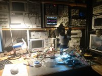
That's a cool looking lab you have there. I'm still collecting equipment for an RF lab. I had one of those Leica microscopes on my desk at work, as well as all the hot air reflow tools, and a PCB fab and assembly lab in house, but that's all gone now. The plant is all but closed down. I got an old Bausch And Lomb scope, still collecting other tools.
Hah. You have a SDRplay box - you don't miss anything do you! I find the box gets overloaded easily. I'm using loop antenna for both tx and rx (urban dweller) and even then the SDRplay shows symptoms of a severely overloaded front end (spurs everywhere on the waterfall). I await your report on how this box performs close to that public service tx site at high local elevation! I also had a Peaberry SDR 2 - which I blew up by accident. It was an exceptionally awesome receiver that I miss a lot. It went away due to parts shortages. The designer had a stable board and a well prepared kit but the parts supply madness eventually ended a good thing.
AE9RB • View topic - Peaberry Project Status
Where I live, in the city, on the flight path inbound for Logan (BOS) traffic, I can hear very little except late at night. Mind you, I can be heard - even at 1 or 2 W - from Boston to Belgium, but I can't hear others unless its late at night. Even then, I have to use a outdoor, remotely tuned antenna. My TX antenna is a manually tuned Alexloop 7-30. In my kitchen window, using WSPR on the qrp-labs kit or an FT-817 ; I can get spots reliably in Belgium. But the only way to hear them is to put a remote, varactor-tuned shielded ferrite loop (B field) out in my backyard and wait until about midnight - at which point I can spot at 80m or 160m WSPR or in Winter time (now), tune in nicely to the local AM 80m net chatter.
I've been using a Ramsey Labs Signal Magnet (now defunct) modified for 160m/80m - and another coil that I swap out for 40m/30m. However, my next goal is a remote, varactor tuned loop based on this:
http://home.earthlink.net/~christrask/Varactor%20Tuned%20Loop%20Antenna.pdf
In your WV holler, can you run some Beverage antennas? Do you have enough
woods or property clearance for such things. That's the dream!
-- Jim (AB1RW)
Tubelab_com said:You will need a bandpass element there, probably a crystal filter. Just as with the receiver there will be an image in the transmitter. ..... A filter is needed to kill the 44.09 MHz image from the mixer. Since the image is only 910 KHz away, a simple LC filter will not be sharp enough.
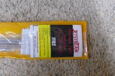
These 45 MHz filters are dirt cheap, < $4 including shipping, so I bought one. The data sheet is attached.
Tellurian Technologies 45MHz Crystal Bandpass Filter T45U15BG (Matched Pair) | eBay
Am I correct in assuming that as regards these monolithic filters, the industry standard nomenclature is that an "A" suffix in the filter designation indicates a two pole filter, while a "B" suffix indicates a series pair of two "A" filters to make a four pole filter?
These Tellurian filters show a -60 dB 910 KHz response with a two pole filter, and -90dB for the four pole configuration. The ECS45K20A I purchased earlier looks to have a -65dB 910 KHz response. I am assuming any of these is going to put the TX image far enough down, especially considering there will be subsequent low pass filtering, and with a mobile antenna, that is a pretty sharp filter on its own?
Since it's the holiday season, I'll be spending most of the next six weeks at our second house, so I'm back to working on paper, again, and not likely to make any hardware progress on this project .... Might get a chance to do some work on the stereo receiver project. Still need to decide on high or low power.
Win W5JAG
Attachments
I am assuming any of these is going to put the TX image far enough down
I don't know what the current FCC requirements are for spurious TX product rejection is in an HF ham transmitter, but they used to be pretty loose.
The radios we built were held to a -80db spec for ALL unwanted TX emissions, including harmonics. These however were "mission critical" public safety radios where someone's life could be on the line if the radio didn't work.
As you state -65 plus antenna rejection is probably OK.
For $4 per set, I'll probably get some of these too.
while a "B" suffix indicates a series pair of two "A" filters
I don't know if this is always the case since the "C" six pole filter is a single package.
For $4 per set, I'll probably get some of these too.
Yeah, I already regret only getting one set. I'll also order more. That fellow has a lot of neat stuff.
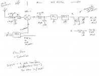
Proposed first front end with a ring mixer. Looks too simple, but I guess that's the virtue.
The T Network ahead of the mixer is a low pass filter at about 26 MHz. It doesn't have much attenuation until the bottom of the FM band, and then only about 30 dB. I anticipate the antenna will be a pretty sharp filter in it's own right.
The LC network out of the mixer is to match into the Tellurian filter(s). If I use the ECS, I'll recalculate the values. I'll use a homemade 45 MHz IF transformer from a toroid to match into a MOSFET IF amp, or another LC network to match straight into a Lo-Z bipolar transistor, or IC amp - or maybe no matching needed, depending on what I use here.
Haven't thought much about the first IF amp - it seems all I want to do here is maybe cover the loss ahead of it, and in the mixer to follow.
I'll probably work up another sheet for active mixing, since it may be a bit before I can burn solder on the project.
At HF, I'm thinking I won't need an RF amp, but I guess that could change once something is built out enough to get in the car and start testing. My usual test is that if I can hear the noise output increase when an antenna is connected, sensitivity is adequate .....
I guess I will actually look at Part 97 and see what the HF spectral purity requirements are, but I can't imagine -60 dB not being sufficient for amateur use. Not that I will have any way to directly measure ...
Win W5JAG
Attachments
Last edited:
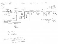
It is absolutely essential that the RF and IF ports of the ring mixer
see 50 Ohms without reactive components. Anything that is reflected
back into the mixer will mix again and again and again. So the IP3
drops to ridiculous values.
That has been discussed for over 30 years in CQ-DL. QST, QEX,
Ham Radio and other publications.
73, Gerhard
see 50 Ohms without reactive components. Anything that is reflected
back into the mixer will mix again and again and again. So the IP3
drops to ridiculous values.
That has been discussed for over 30 years in CQ-DL. QST, QEX,
Ham Radio and other publications.
73, Gerhard
It is absolutely essential that the RF and IF ports of the ring mixer
see 50 Ohms without reactive components. ....
The point is well taken.
I think the RF port is OK - it should be looking at a constant 50 ohms. I can insert a broadband 50 ohm resistive pad at the IF port to terminate it.
The antenna will be a small mobile whip - Yaesu ATAS-100 - about 4 feet in physical length. If I use the ring mixer, I'm hoping to avoid the need for an RF amplifier, so I hate to add in more conversion loss, if I don't have to. I may need more poles at the low pass filter - going to 5 poles would give me another 30 dB rejection at the image, but would be more loss.
If the mixer is not going to be seeing big signals, is it that critical that the mixer be terminated at all frequencies, as opposed to just being impedance matched at the 45 MHz IF?
All of this is part of the balancing I am weighing between active and passive mixing.
Win W5JAG
It is absolutely essential that the RF and IF ports of the ring mixer
see 50 Ohms without reactive components.
Revised. Better?
Attachments
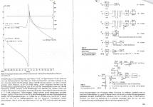
From an article by DL7VY in a 1974 DL-QTC:
Left side of the picture:
input impedance of a 8 pole 9 MHz crystal filter. XF-9B by KVG, it was the
standard here for ham receivers. The impedance goes all over the place.
Very bad as a mixer termination. There is no reason to assume that the
45 MHz filters are more friendly.
On the right side: some alternative terminations and their influence on
3rd order Intercept point. By far the best solution is an isolation amplifier
between the mixer and the filter. Its input impedance is 50 Ohms real
over a wide frequency range.
You probably cannot get the Teledyne CP643 any more, nor the
TI P8000 or P8002. The input impedance in common base is 1/gm,
so you need gm=20 mS. Modern FETs such as BF862 have a better gm
at less current than the CP643. You can use several in parallel to get
enough current for linearity and then get rid of the excessive gm by a
negative gate voltage. I think the old FETs used to run at 50 mA.
I happened to measure one of them when I started to play with my
new Locky-Z curve tracer
< http://www.diyaudio.com/forums/grou...measurement-amp-ikoflexer-11.html#post5195602 >
The isolation amplifier will have some gain, but after the input filter and
the 6+ dB of mixer loss that should be no problem. It can handle the
crystal filter mismatch, esp. with a parallel resistor so that the impedance
cannot go completely through the roof.
There are now op amps > 46 dBm IP3.
Two AD604 make a great IF amplifier with excellent AGC range.
Article by U.Rohde in Ham Radio 1975:
< https://www.google.de/url?sa=t&rct=...put%20RX.pdf&usg=AOvVaw0_mXhiyhkZzT4rC__vU6iu >
Look into the archives of QEX at ARRL.
Attachments
Last edited:
Article by U.Rohde in Ham Radio 1975:
I have a lot of Dr. Rohde's articles from the 70's into the 90's, from Ham Radio and QST, but did not have that one. Thanks for posting it, Gerhard. I should probably read his book, since I have it ....
There was a follow up article in Ham Radio in 1977 ( don't have the cite handy ), not by Dr. Rohde, but referencing the 1975 article you linked, that illustrated an adaptation of (e) above - an extensive 50 ohm bandpass at the RF port, followed by a constant 50 ohm impedance FET amplifier at the IF port. This was for a strong second conversion mixer, but same principles.
The simple diplexer at the input in the revision is from Solid State Design for the Radio Amateur, ARRL.
I fear 30 dBm intercepts may be beyond my current skill set at the moment.
If only there were a magical snake oil goop that could simply be mixed up and slathered all over the mixer case by RF dolts, and instantly match the ports at all frequencies ....
Win W5JAG
Methinks it is no longer that important to have those high intercept points.
Radio Tirana, Bejing & others are no longer in our 40m band, last time
I looked, which was quite a time ago, and we get new bands because
nobody wants them any more. That 1.6 MegaWatt Medium Wave monster,
"Europawelle Saar" that was 10 miles away from my home, on
1422 KHz is also gone. Europe has been FM land for quite
some time and is converting to digital now.
There are now op amps that can do all sorts of miraculous things,
like < http://www.ti.com/lit/ds/symlink/opa846.pdf >. This would
have an IP3 of 45 dBm after a mixer on 9 MHz. That used to be
impossible. It simply does not distort until the output hits the
supply rails, so to speak.
A friend of mine has built a huge EME array for 432. 10W and
10 dB antenna gain should be enough to contact him. Next summer
I'll be in Scotland, Isle of Skye or so, and I'd like to give him some
new squares. I'll travel with a motorcycle, so I need a transceiver that
fits a cigar box. I'll have a Dell XPS-13 notebook with me.
I probably will use a Red Pitaya as an SDR and build down/upconverters
with a 100 MHz crystal*4, mixers and SAW filters for 432, a no tune solution.
Still undecided abt. the PA and Li batteries.
Bed time!
Gerhard, DK4XP
Last edited:
- Home
- Member Areas
- The Lounge
- No RF gear here?