I came away thinking that it was an excellent design. Maybe that is your safest path to success, especially since you already paid for it!
Indeed, no doubt it's the safest ( and smartest ) path, and it's not getting any younger, either; there is a revised version out now. It would be impossible for me to build anything approaching the DZ level of complexity, except as a pre engineered kit. I have the parts for both versions of the original Sienna - the blank panel, remote pc control version, and the full front panel kit, and all the filters that are best installed at the initial build out.
It has an interesting architecture - best that I recall it uses 70 MHz as the first IF, then 9, then 455, and both of those LO's can be moved around for IF shift and variable bandwidth. The TX strip uses 10.7 MHz, I think, so not much, if anything, in common with the RX strip.
I swung by the office and found I do have one of Rohde's books: Communications Receivers, Principles and Design (first edition) by Ulrich Rohde and T.T.N. Bucher.
The site has obviously scanned my computer and figured out I'm in the wading pool. I get ads for stuff like $25 dollar oscilloscope kits

Win W5JAG
I get ads for stuff like $25 dollar oscilloscope kits
I bought one of those kits, only it was cheaper, like $19, but it was a over year ago. It, like your DZ, still sits unbuilt. I will get to it some day. It will make a cute little music synthesizer module.
I do have one of Rohde's books:
I met him about 10 years ago. We needed a really good VCO design for a design concept, and if it made it to production, would have been a nice lucrative contract for the vendor. Most of our radios have a 10 year product lifecycle. Rohde had a VCO company at the time, maybe he still does, I don't know. He lives in Germany most of the time, but it turns out that he has the entire top floor of a high end condo on Marco Island Florida and I had just returned from a vacation there. I remember walking past the condo on one of my long beach walks. We wound up using somebody else's VCOs due to size constraints that Rohde couldn't meet with his push pull design.
(DZ) has an interesting architecture - best that I recall it uses 70 MHz as the first IF, then 9, then 455, and both of those LO's can be moved around for IF shift and variable bandwidth.
The DZ was one of the first good up conversion designs. The first filter is at 70.455 MHz and a fixed 4 KHz bandwidth. That limits the bandwidth into the second and third mixers. At least on the schematics I have (2010) the 2nd and 3rd LO's are fixed at 61.455 and 9.455 MHz. The TX appears to be a single conversion system with the IF at 4.915 MHz. With the parts shortage as it was back then the frequencies could have changed a few times to suit what was available.
My plan back then was to up convert to 45 MHz. then convert to 8.2 MHz, 9 Mhz or 10.7 MHz for demodulation, depending on mode, to suit available filters. I had purchased two sets of 200 Hz CW filters at 8.2 because they were common and relatively cheap. My TX would just reverse the path through the same filters. VHF and UHF used the existing setup with another conversion from a higher IF (315 MHz or 1260 MHz) to 45 MHz. I started building some of the basic blocks, and I have recently found most of that old work.....now if I could only remember what I was thinking at the time.....
Another good radio of the day worthy of study is the Elecraft K3. It is not known for having a great TX, but it's RX was great for 2009. It used a PLL / DDS combination for a very clean LO. It also used a DSP for demod and modulation of a 15 KHz IF for both TX and RX.
> The site has obviously scanned my computer
Just to put blame where it belongs....
DIYA does not scan your computer. DIYA is supported by ads from external servers. When those servers get the call for an ad, they look at the page which called the ad ("What is on that page?") as well as your ad-page-history on other sites using those same ad servers, and picks an appropriate category of ads. (Google is the expert at putting such clues together, but all the ad-houses do similar things.)
At least on the schematics I have (2010) the 2nd and 3rd LO's are fixed at 61.455 and 9.455 MHz. The TX appears to be a single conversion system with the IF at 4.915 MHz.
Not sure where I came up with 10.7 for the TX IF; the block diagram I have shows the same frequencies as your schematics. The promotional literature says full passband tuning at both 9 MHz and 455 KHz; the operating manual says:
"IF Shift [IS]: As with position 1, select either IF by pushing the Adjust
knob. Turn the knob to slide the selected filter right or left.
The overlap between the two trapezoids is an approximate graphical
representation of the resulting bandwidth. Position 2 allows the shift
to be set in 50 Hz increments per step of the Adjust knob. Position 3
is 100 Hz per step. Position 4 is 250 Hz per step."
The TX IF can also be shifted from the setup menus. And there is this:
"Enhanced SSB: Off, On. If enabled, the transmitter’s wide bandwidth filter is used in SSB mode. Receiver bandwidth is unaffected and must be selected manually with the filter controls."
Enhanced SSB is 6KHz.
I would think the DZ is about the most complicated kit ever marketed to Hams. I was going to upload the catalog, but the pdf files is too big, and I don't have software here at the house to pull the Sienna pages, and shrink the size.
Win W5JAG
> A little.
> Maybe.
> No, not really.
Dangerous answer.
See for yourself: < Dirty Harry (10/10) Movie CLIP - Do l Feel Lucky? (1971) HD - YouTube >
Since cost at Chinese levels is an argument, one would probably choose the SRA1H
from the junk box.
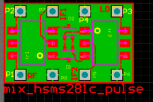
I have made mixers from Pulse CX2147 transformers and HP/Avago diodes, or
whatever they are called at the moment. IO pins are on 100 mil centers, so they
can be easily deployed on vector board or such. 7 dBm only but with known diodes,
which is important for my purposes.
There are other interesting transformers from Pulse and MAcom, all from Digikey
and/or Mouser. Quite cheap. CX2147, cx2049, cx2074nl, cx2156, maba009594,
mabact0059, mabaes0060, mabaes0061, cx2032nl e.a.
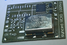
I have developed quite a library of stamp sized functions like this,
100 MHz VCXO locked to 10 MHz ref frequency.
4046 (in SO16) and LVDS input buffer were not yet needed in this case.
There are also inv /non-inv OP27, regulators, PIN attenuator macros and such.
Divide and conquer.
Also the board process is quite fast with presensitized material, less than
90 min. from drawing in computer to drilled board.
<My version of the G = 1000 low noise measurement amp (for Ikoflexer). >
The Rohde/Bucher book contains everything that's needed.
> Maybe.
> No, not really.
Dangerous answer.
See for yourself: < Dirty Harry (10/10) Movie CLIP - Do l Feel Lucky? (1971) HD - YouTube >
A ring mixer is the hot ticket, but they don't have to be made with diodes. Fet mixers have become the first choice recently. For HF a fet mixer can be made with analog switch IC's.
Since cost at Chinese levels is an argument, one would probably choose the SRA1H
from the junk box.
I have made mixers from Pulse CX2147 transformers and HP/Avago diodes, or
whatever they are called at the moment. IO pins are on 100 mil centers, so they
can be easily deployed on vector board or such. 7 dBm only but with known diodes,
which is important for my purposes.
There are other interesting transformers from Pulse and MAcom, all from Digikey
and/or Mouser. Quite cheap. CX2147, cx2049, cx2074nl, cx2156, maba009594,
mabact0059, mabaes0060, mabaes0061, cx2032nl e.a.
I have developed quite a library of stamp sized functions like this,
100 MHz VCXO locked to 10 MHz ref frequency.
4046 (in SO16) and LVDS input buffer were not yet needed in this case.
There are also inv /non-inv OP27, regulators, PIN attenuator macros and such.
Divide and conquer.
Also the board process is quite fast with presensitized material, less than
90 min. from drawing in computer to drilled board.
<My version of the G = 1000 low noise measurement amp (for Ikoflexer). >
The Rohde/Bucher book contains everything that's needed.
Attachments
Last edited:
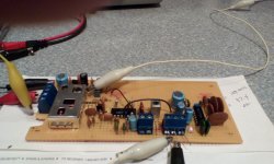
.... I have been thinking about slapping together a quickie FM tuner for football season ....
And done, with time to spare.
Prefab FM tuner module cut the time in half, probably. CA3089 FM receiver chip, LM1310 stereo decoder. AGC and AFC from the CA3089 applied to the tuner module.
Antenna will be something circularly polarized, probably a turnstile, on my roof tower.
The first variant used an MC1350 IF amplifier between the tuner and the chip. This worked well, but had a pretty big footprint on the board, and more gain than needed. It was not directly compatible with the AGC from the CA3089, adding some complication.
I removed it, moved the CA3089 closer to the tuner, and, of course, decided that provided inadequate gain, when the loss of the ceramic filters is about 12dB. So, I shoehorned in a 2N2222A, which looks to be about right. The first variant on that used transformer coupling to the second ceramic filter, but ultimately I just went with the ceramic filter as the load for the IF amp.
It's shown connected to the stereo decoder, but I also have the mono de emphasis network on the board that I can use. The decoder gave me a bit of trouble. I didn't have the right capacitors, so I had to parallel stuff to get close. At first, I couldn't get the onboard oscillator down to 19KHz, so I had to tweak the VCO values a bit. Once I had a good clean square wave at 19KHz, the PLL locked right up when it detected a pilot tone. The decoder is mostly the data sheet circuit; I returned the de emphasis caps to ground instead of the positive rail, because it was easier to fit them that way. It's wired for unity gain, which seems adequate to drive the small push pull amp, with just a low gain 12AU7 front end, built as part of the removing MOSFET's thread in the Tubelab sub forum.
The empty space across the top is to channelize the tuner - I am only interested in four or five stations - and hopefully an audio switching setup to switch the tuner and another aux input in and out, so it can be installed in a Tubelab amp.
Win W5JAG
Attachments
....
No sign of my DDS yet, though. ...
I had given up on finding it, and then I found it. While rummaging through a bunch of cabinet boxes, and other enclosures in anticipation of a different project, I found it stuck in a plastic enclosure - probably I had put it in there testing for preliminary fit and layout with some other stuff.
I powered it up, and it came up at 10 MHz. At this point, I have no idea what I was thinking of when I selected that firmware. Maybe a DC CW transceiver for 30 meters, or maybe I was going to mix it somewhere else. Or maybe I just wanted to play with a DDS. The LCD display and encoder were also found with the DDS, so I'm good to go .... for something ......
Win W5JAG
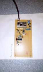
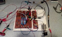
... Reworking my original very simple rig, about 90% of which still exists, and using it as a tunable IF - my original plan - is starting to look better ....
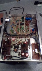
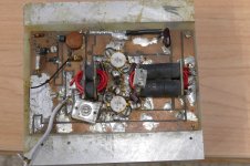
Powered up for the first time in twenty five years. The original metal chassis/ cabinet, shielded enclosures for the oscillators, etc., are long gone. I've seen some shocking clip lead fur balls, this is one of the worst I've perpetrated. This implements minimum function for the receiver - didn't fool with the TX components.
It still works.
The LC LO has got to go - it wasn't great back then, and time hasn't helped it.
The carrier oscillator looks good - it came right up at 455.0 KHz, rock solid, 0.5 V RMS sine wave, very clean.
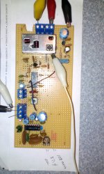
I think the front end ( need to add another pole of filtering ), mixer, and USB / LSB filters and switching are OK. Looking at some of my drawings. I had a few wait ... what? moments. The matching into the IF, around the tail end ceramic filter, and some of the component values in general can be improved on. Level matching of the CO into the product detector also looks bad - way too strong, and needs to be attenuated, a lot. Basically everything behind the filter and in front of the final audio pa stage looks ripe for rework.
There's room on the board for a completely new IF / audio strip, if needed.
Lot of other projects going on, and I don't really need this, other than for learning purposes. I'll look at the TX after I get the receiver sorted.
Maybe begin an up converter after I get this one right.
Win W5JAG
Attachments
Last edited:
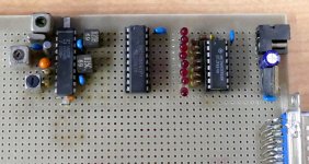
While digging through boxes of stuff looking for some old TSE boards I found an old project from the early 90's. It has a pair of digital chips connected to a parallel port DB25. In that era I was writing code for PC projects that ran on Windows 3.1 with Borland C. It was easy to read and write SPI uning a few pins on a parallel port with some canned Borland code.....those days are gone.
The board also has a complete IF strip including a RSSI (Received Signal Strength Indicator) capable of 90 db of dynamic range. That's where the test board stopped, and that was lilkely the end of the project, but those 3 chips plus a few foggy memories tell me where it was going. This was going to be a PC based RF spectrum analyzer. My guess is that the project terminated when two new PC operating systems came along, Windows 95, and OS2 Warp. Borland didn't make simple, cheap C compilers for either.
To my surprise the SA605 chip is still available in SMD only, so if the 455 KHz filters are available, SMD would be OK, this still may be a valid project.
Attachments
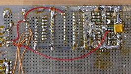
I had to look that chip up, hadn't run across it before. I think the SA602/SA612 mixer chips are also now obsolete in through hole, but may still be available as SMD. The elderly CA3089 was available as an smd part before it finally bit the dust. Interesting how you did the ground plane around it on that vector board.
I think 455 KHz through hole filters are marked obsolete, but stock may still be available. 455 KHz IF transformers are still available. 10.7 MHz are gone.
I used MC3357 for my FM rig, which is probably obsolete now, but I have a few stashed. The RX strip was built on a board for a 10m FM receiver that ran in QST, but I couldn't make it work to save my life. I wound up just building my own receiver around the miniscule bit of that board that worked. The TX strip is a GLB kit. I added a control board to make it a four channel scanner. I actually still use this radio. I don't have any of the drawings, but I found some drawings on an eight channel vhf/uhf scanner I made about the same time for a girlfriend that was pretty similar, but used a later chip ( MC3361? MC3363?).
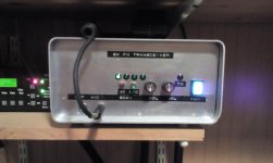
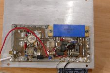
Poking around in the warehouse of junk, I found this Den( junk )tron utility transceiver that I bought for peanuts years ago. I brought it home and opened it up, and this thing has a Mizuho SG-9 SSB board in it. It's a complete 9 Mhz SSB system, all of the AF and RF on one board. Dentron just tacked their front end unto this board. The brick is 250 watts input, and it is driven from the output of a 3N204 mixer - probably a couple of milliwatts. I powered it up, and the RX works. Didn't test the TX.
So, I think when I move on to the up converter, that Mizuho board is my play for the 9 MHz IF and AF, and that brick will be the PA.
Win W5JAG
I think 455 KHz through hole filters are marked obsolete, but stock may still be available. 455 KHz IF transformers are still available. 10.7 MHz are gone.
I used MC3357 for my FM rig, which is probably obsolete now, but I have a few stashed. The RX strip was built on a board for a 10m FM receiver that ran in QST, but I couldn't make it work to save my life. I wound up just building my own receiver around the miniscule bit of that board that worked. The TX strip is a GLB kit. I added a control board to make it a four channel scanner. I actually still use this radio. I don't have any of the drawings, but I found some drawings on an eight channel vhf/uhf scanner I made about the same time for a girlfriend that was pretty similar, but used a later chip ( MC3361? MC3363?).
Poking around in the warehouse of junk, I found this Den( junk )tron utility transceiver that I bought for peanuts years ago. I brought it home and opened it up, and this thing has a Mizuho SG-9 SSB board in it. It's a complete 9 Mhz SSB system, all of the AF and RF on one board. Dentron just tacked their front end unto this board. The brick is 250 watts input, and it is driven from the output of a 3N204 mixer - probably a couple of milliwatts. I powered it up, and the RX works. Didn't test the TX.
So, I think when I move on to the up converter, that Mizuho board is my play for the 9 MHz IF and AF, and that brick will be the PA.
Win W5JAG
Attachments
Last edited:
I had to look that chip up
The part in my board still wears the Signetics logo. When was the last time you heard that name? Someone has to be still using that part or it would have vanished long ago. It is still reasonably priced, and on rev 5 of the data sheet, so it has to be selling in volume to someone. My guess is the remote telemetry (power meter reading) people. The meters in residential areas use low cost low powered mesh technology, but the rural areas need "backhaul" from a cluster to a fiber trunk. This may make it live on for a while longer.
I used MC3357 for my FM rig, which is probably obsolete now
Most of those parts were never picked up when Motorola shed their semiconductor division.......twice!
The linear stuff would have gone with ON semiconductor, but they just shipped from stocked wafers on the low volume parts. Many were never actually fabbed at ON, but they did get some profitable stuff made through TSMC. Motorola later shed the rest of their semiconductor division as Freescale, a spinoff.
I used the MC3357 in a satellite TV receiver. That chip will reliably demodulate a 30 MHz wide FM channel with a 100 ohm resistor across the quadrature coil!
... Signetics logo. When was the last time you heard that name?
Still have Signetics stuff with the NE prefix. There should be some NE prefix parts in the scanner circuit for that 2M rig. I think the only SA parts I have are some SA612. Which were NE602. Or something like that.
What bugs me about the semi stuff is not that it goes obsolete so quickly, it's that it virtually disappears when it goes obsolete - like it just goes straight to a landfill instead of a surplus house.
I'm almost giddy about discovering that SG-9 board and that brick. I hope the brick still works, or isn't fried too badly.
With a working 9 MHz SSB rig for the starting base, I am now strongly considering blowing off the old rig, and just going straight to an up converter, with a 9 MHz second IF. Maybe start with a single band, and add additional bands later.
I'm having difficulty grasping the merits of refining and optimizing something that I would likely immediately abandon for something more advanced. The only real question is do I part the old rig out, or just leave it intact for now ( Except that LO - that thing is parts either way ... )
Win W5JAG
A friend of mine has a 10 KILOWATT water cooled solid state ISM amplifier for 13.56 MHz and a 1 kilowatt solid state amp for 400 to 450 MHz waiting for me in Florida. Unfortunately I need to come pick them up and bring a vehicle bigger than a small car. I have planned 3 trips to Florida since July, and all have been killed due to reasons from Hurricane Irma to finances, so they will likely wait until next year if they don't get sold for scrap in the mean time.
That 10 Kw amp is most certainly made of lower powered modules which would be awesome on 20 meters, and maybe more. I haven't seen it. I have been told that it weighs more than me.
The 1 Kw 432 MHz amp IS made of 11 100 watt modules (one driving 10) and combiners. I haven't seen it, but I have one of the modules from a second unit that lost a battle with a forklift. It puts out 60 watts when driven by an old style Yeasu FT-817 (about 5 watts on 432).
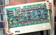
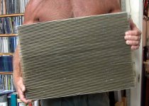
I got some surplus MRI amplifiers in Dayton several years ago. I took one of the small (1KW) ones apart and fired up one of the individual modules. It will cover 40 meters through 20 with 100 watts or more output, and 80 through 10 at 80 watts or so at reduced efficiency. It seems that the ferrite combiners get hot when operated outside their design frequency.
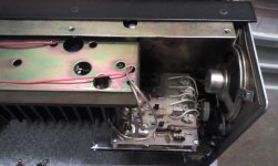
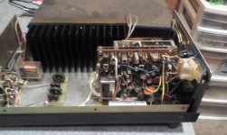
The first two pictures show a big (2.5 Kw) MRI amp that I got in Dayton for $50. I took the PC board off the heat sink (which weighed about 40 pounds) and sold the heat sink at Dayton the following year for $50! The buyer wanted to build a class A mosfet based audio amp. I still have the PC board, but haven't played with it yet.
I found two "bricks" while digging through my old stuff in the past two days.
The first was a 50 watt amp for 432 MHz. I was using it for ATV at about 20 watts peak. It wasn't linear enough to be pushed any harder without saturation causing loss of sync.
The second was a 2 to 30 MHz RF amp I built in the late 70's. When driven with a "5 watt" radio on 12 volts, it made about 100 watts and would not blow up with any load, even a short or an open. Driven a bit harder and run on a 36 volt supply about 250 watts flowed out. It would blow up in a spectacular manner at this level, usually blowing the covers off the output devices. The transistors in each amp were house numbered parts. Who knows what they really were.
Neither of these have seen power since the early 80's. The ATV repeater we used ate a lightning bolt and was never rebuilt. We used to "text" each other on ATV by connecting an Apple II clone's output to the PC electronics ATV board. Some hams might have engaged in video games through the repeater too. I sold the ATV setup at the Miami Hamfest shortly after that, but kept the amp. The buyer already had a better one.
That 10 Kw amp is most certainly made of lower powered modules which would be awesome on 20 meters, and maybe more. I haven't seen it. I have been told that it weighs more than me.
The 1 Kw 432 MHz amp IS made of 11 100 watt modules (one driving 10) and combiners. I haven't seen it, but I have one of the modules from a second unit that lost a battle with a forklift. It puts out 60 watts when driven by an old style Yeasu FT-817 (about 5 watts on 432).
I got some surplus MRI amplifiers in Dayton several years ago. I took one of the small (1KW) ones apart and fired up one of the individual modules. It will cover 40 meters through 20 with 100 watts or more output, and 80 through 10 at 80 watts or so at reduced efficiency. It seems that the ferrite combiners get hot when operated outside their design frequency.
The first two pictures show a big (2.5 Kw) MRI amp that I got in Dayton for $50. I took the PC board off the heat sink (which weighed about 40 pounds) and sold the heat sink at Dayton the following year for $50! The buyer wanted to build a class A mosfet based audio amp. I still have the PC board, but haven't played with it yet.
I hope the brick still works, or isn't fried too badly.
I found two "bricks" while digging through my old stuff in the past two days.
The first was a 50 watt amp for 432 MHz. I was using it for ATV at about 20 watts peak. It wasn't linear enough to be pushed any harder without saturation causing loss of sync.
The second was a 2 to 30 MHz RF amp I built in the late 70's. When driven with a "5 watt" radio on 12 volts, it made about 100 watts and would not blow up with any load, even a short or an open. Driven a bit harder and run on a 36 volt supply about 250 watts flowed out. It would blow up in a spectacular manner at this level, usually blowing the covers off the output devices. The transistors in each amp were house numbered parts. Who knows what they really were.
Neither of these have seen power since the early 80's. The ATV repeater we used ate a lightning bolt and was never rebuilt. We used to "text" each other on ATV by connecting an Apple II clone's output to the PC electronics ATV board. Some hams might have engaged in video games through the repeater too. I sold the ATV setup at the Miami Hamfest shortly after that, but kept the amp. The buyer already had a better one.
Attachments
A friend of mine has a 10 KILOWATT water cooled solid state ISM amplifier for 13.56 MHz ....
You could use the heat exchanger for that amp to heat your lab. Sounds perfectly sensible to me. One of our locals is (in)famous for bellowing: "1000 watts IS qrp!" at one of our club meetings.
I'm dubious that the PA in that Dentron is a real 250 watts, but inside the cabinet was a couple of pages of specs and schematics that says 250 in, 135 out. What got me giddy was seeing the milliwatt level drive going into it.
I guess I need to start looking on Ebay for some DDS / Synthesizer boards.
If these are anything like the Chinese class D audio boards they may be anywhere from somewhat useful to junk.
I just bought one of the RV3YF DDS' from the eBay store:
Single band DDS VFO 0..160 MHz for HF Transceiver. Assembled. | eBay
Looking at his website, it looks like it has one fixed output between 1 and 160 MHz, and one variable output between 1 and 160 MHz. That ought to cover about all the possible combinations of up, down, and direct conversion, considering the SG-9 has its own BFO, and won't need that fixed output from the DDS ...
I found the manual for that Mizhuo SG-9 board on the DK Mods website.
Looks like the DZ is safe in its box. The one good thing about having the attention span of a gnat is that I can juggle a lot of projects at one time. They just take longer ....
Win W5JAG
Last edited:
"1000 watts IS qrp!" at one of our club meetings.
I know a ham who refers to the 1500 watt legal limit, as "I run 1500 watts....per driven element." I have never seen his shack, so I don't know what he really has. I know another guy in Florida who has some old military stuff capable of running 10 KW on HF, again I have never been there but the pictures of his 25 X 45 foot "shack" look awesome.
bought one of the RV3YF DDS' from the eBay
It used the Si5351a chip from Silicon Labs. I think that's the same chip used in the Soft Rock SDR rig. I played with those a few years back. They are clean enough for a decent rig, but the phase noise is not quite good enough for close in CW contesting if you are into that sort of thing.
The DZ was one of the first good up conversion designs. The first filter is at 70.455 MHz and a fixed 4 KHz bandwidth.
At the time Brian introduced the DZ for sale, the 4.5 KHz 6 pole 70.455 filter was an option, and the stock filter was a 2 or 4 pole item.
I looked at my invoice, and I bought the upgraded 6 pole filter, and I just verified that it is in the box. So, unless Brian pulled the stock filter out of my kit, it is possible that somewhere in that vast sea of stuff that makes up the DZ kit, I have an uncommitted 70.455 filter.
The SG-9 should have a filter centered at 9.000 MHz, and a BFO crystal at 8.9985, which should be passing the USB.
If my memory is correct, the sidebands stay in their proper relationship, so long as I use an injection frequency *above* the frequency to be converted? In other words, sideband inversion occurs only when the lo frequency is below the frequency to be converted?
I was doing some arithmetic on a napkin and that looks like that holds true at all frequencies for single conversion, but it has been a while since I have done this, and I haven't looked at how multiple conversions might affect this. I do have sideband inversion in my rig on the breadboard - LSB defaults to the USB filter.
The DDS is marked shipped with a Dec 25 receipt date, so I've got a while to work through this .....
Win W5JAG
It used the Si5351a chip from Silicon Labs. ....They are clean enough for a decent rig, but the phase noise is not quite good enough for close in CW contesting if you are into that sort of thing.
Pretty sure that won't be a problem ....
What kind of output level will these do? Enough to drive something like a mini circuits ring mixer directly?
Win W5JAG
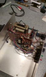
I hope the brick still works, or isn't fried too badly.
And .... it's FRIED. The push pull output pair gets it's B+ direct from the power terminal without so much as a smidgen of protection, no fuse, looks to have no foldback protection, just ...disaster waiting to happen .....
Hooking 12 volts up to the output pair made my power supply groan in delight so I'm sure the output transistors are a dead short. No indication on the schematic what they are - probably the old helicopter type. Likely the cheapest junk they could get away with .....
Now I know why it was cheap!
Win W5JAG
Sparkfun and/or Adafruit carry breakout boards for some popular small SMT chips, and they're the cheapest such boards I've seen. I haven't looked on eBay for Chinese equivalents, but 100 percent of the breakout boards I've ordered and used from Sparkfun and Adafruit have worked, so there's that.My initial plan is to use a canned mixer (I have several) and a frequency synthesizer (EBAY Chinese PLL and DDS boards on their way)
Here's the one DDS chip on a breakout board I've found:
Adafruit Si5351A Clock Generator Breakout Board - 8KHz to 160MHz ID: 2045 - $7.95 : Adafruit Industries, Unique & fun DIY electronics and kits
These boards (especially from Adafruit) also have good instructions on how to wire up to an Arduino and code libraries and example code (that works!).
.... Then upconvert to 45 MHz where you gain some filtering in the crystal. You can then convert directly to 455 KHz .......
The DDS is now in the hands of the USPS, so I assume it will show up in the not too distant future.
I've been thinking about this, and going directly from the LO VHF IF to 455 KHz is looking pretty good to me, if this is actually a feasible scheme. Most of the commercial rigs I am familiar with always seem to use an intermediate IF on the way down.
The advantages are that I can use my existing Collins Mechanical Filters; I don't have to get involved in the details of sideband inversion / no inversion / moving the carrier oscillator around since I have a filter for each sideband; I can skip a mixer and filter; I can use my existing 455 KHz LO which still looks pretty good; and I can potentially use a significant chunk of the existing transceiver board, although I may wind up building a new 455 KHz IF strip. Since 455 KHz is so easy to work with, I could have a separate strip for FM and AM making the receiver, at least, multi mode. I have a lot of that stuff already built up and de bugged from previous projects. That would also give an early taste of partial success, which I think is good for long term projects with a learning curve.
I've attached the LO / Image frequencies for a 45 MHz IF - hopefully I got these right.
Starting with just a simple receiver strip, it looks like a single 30 MHz Low pass filter is adequate for HF reception to 30 MHz. If I expand it out to VHF, a Low Pass filter is adequate for 6 meter reception, but I would need to use a band pass filter for 2 meters because of the way the LO falls. Once the TX strip is added in, then the Lo Pass filter for each TX band would be used for the receiver front end, except 2 meters.
You guys see any glaring flaws with this? I want to wind up with a real transceiver, usable on the air, even if it is minimalistic, feature wise. I don't want to put a lot of effort into it, just to wind up with a toy.
BTW, as part of the due diligence on this, I ran across a QST article by Rohde, around 1991 or so, and he calls that low VHF filter a roofing filter. I wonder if that is where the term got started.
Win W5JAG
Attachments
- Home
- Member Areas
- The Lounge
- No RF gear here?