Yeah, I agree. Certain "pop music" has a narrow bandwidth and low dynamic range.
That describes FM BCB around here almost perfectly. Massive compression and excessive pre emphasis. I have been thinking about slapping together a quickie FM tuner for football season, and the terrible broadcast quality around here looks to make the task a lot easier. No need for perfection - mediocrity or worse will be perfectly real world adequate.
Win W5JAG
Going back to the topic, here is my previous RF topic:
http://www.diyaudio.com/forums/analogue-source/292628-high-audio-quality-am-tuner.html
Enjoy.
http://www.diyaudio.com/forums/analogue-source/292628-high-audio-quality-am-tuner.html
Enjoy.
You guys planning your own HF transceivers....I've been intending on building another SSB rig....I have enough boards built up to assemble a single band ( 20 meter ) SSB / CW receiver.....I have some matched LSB/USB filter sets
My initial plan is to use a canned mixer (I have several) and a frequency synthesizer (EBAY Chinese PLL and DDS boards on their way) to convert HF up to a 45 MHz IF (eliminates image problems with the same LPF needed in the TX), then stuff the 45 MHZ IF through a crystal filter (I have several), where it will be converted to I/Q baseband with a Soft Rock board then processed in a PC. VHF will be upconverted to 315 MHz filtered, then converted again to 45 MHZ, frequencies from 200 MHz to 1 GHZ upcoverted to 1206......
315 and 1206 are chosen because there are cheap SAW filters available.
I have a block diagram for all of this on an old hard drive somewhere. It was an idea from a time when the parts weren't common yet, times have changed.
315 and 1206 are chosen because there are cheap SAW filters available.
Does the 1206 still pass 1200.0 (really in the passband, not skirt)?
I'm looking for alternatives in the clock generation of a SDR/TimePod/
PhaseNoiseMeter. The sample rate would be 1200 ...2400 MHz.
10MHz Ref -> Pll 100 MHz VCXO -> *2 *2 -> Epcos 400 MHz SAW ->
tripler -> 1200 MHz SAW -> doubler -> 2400 stepped impedance filter
-> sample clock driver
Now that I can do vapour phase soldering I can use all those new
macho ball grid ADCs with integrated downconverter and CIC filters.
Data will be handled by a Xilinx SOC.
73,
Gerhard, DK4XP
Does the 1206 still pass 1200.0
I posted the number "1206" from memory. It turns out that my guess was wrong. The number I should have posted was 1260. I have a "filters" folder in my SDR parts folder on my hard drive which was made in 2011 when I first started down this road.
The "1260" folder contains 5 different SAW filters whose average center frequency is 1260 MHz. Of those 5 there is one whose specified passband is 1200 MHZ to 1300 MHz, the Triquint 856653. The merger of Triquint and RFMD into a new company, Qorvo had the usual collateral damage and that part is scheduled for obsolescence. Mouser has no stock remaining. Not sure if there is any remaining anywhere.
There are a few others whose lower edge is specified at 1200MHz with some margin for shift over temp. The only stocked part is the RFM / MuRata SF2081E. Mouser has 2400 of them. The center freq is 1220 MHz, 3 db BW is 56 MHz, and the specified IL from 1195 to 1245 is 4 db.
If your filter at 400 MHz is good enough you might be able to get by with a lumped element or microstrip filter at 1.2 GHz if you are only building a few units. Part and PC board variation would make testing and possible tuning necessary unless your PCB was manufactured with tight tolerances on a good substrate.
BTW, I am using a similar clock strategy. 0.5 PPM 26 MHz reference from GSM phone -> slow PLL to 100 MHz VCXO -> *2 *2 -> 400 MHz SAW -> reference input to TI LMX2594 fast PLL (10 MHz to 15 GHz)
The PLL must be run with its phase detector at max frequency for minimum Phase noise / jitter. This is 400 MHz on the new TI chip. Another trick is to run the PLL in integer mode to minimize spurs and move the reference using a DDS. I will eventually explore both paths. I just got a dead HP 4352B VCO / PLL signal analyzer off EBAY. I have to fix it first.
The best 100 MHz VCXO currently is the Crystek CVSS 945 - 100
George, KB4LRE
.....
315 and 1206 are chosen because there are cheap SAW filters available. ....
It's humbling to see the different levels of ambition between trained people, and the rest of us.

My goals are always pretty simple:
1) I can actually make it work ( sort of );
2) it won't drift ( a whole lot );
3) I can actually make QSO's with it, or listen to it all day without having the urge to drive a nail through my ears.
Advancing ( even approaching ) the state of the art is just not on my radar screen.
While digging through my parts last night, I had a stroke of luck and found all of my original documentation ( except the front panel wiring diagram and T/R switching ) for the SSB rig, and half the documentation for the FM rig ( the RX strip and scanner circuits - still have some places I can look for the TX strip drawings ).
Filters. Problematic these days for those of us in the shallow end of the pool. I would like to do an up converter, but the only non HF filter I could find in my junk box was a 60 KHz wide McCoy centered at 30.100 MHz - I don't see that as being any more useful than 9 or 10 MHz. Drake used 48 ish MHz, I think, for the TR-7 and R-7; I'm thinking Collins used around 39 MHz for the KWM/HF 380, but I've never owned one of those. I suppose some of those could be available from junkers. I'm not junking one of my Drakes out, though. it seems like I upgraded the 455 KHz ceramic filters in my Yaesu FT-847 to the Collins mechanical filters, so I may have to look for those old ceramics. They could be better than the CB type Collins filters I have in my little SSB rig.
In a real Mr. Peabody Wayback Machine moment, I found two or three of the old B&W 2Q4 phase shift networks and the data sheet, for another time when filters were prohibitive.
I guess I need to start looking on Ebay for some DDS / Synthesizer boards.
Win W5JAG
> If your filter at 400 MHz is good enough you might be able to get by with
> a lumped element or microstrip filter at 1.2 GHz if you are only building
> a few units. Part and PC board variation would make testing and possible
> tuning necessary unless your PCB was manufactured with tight tolerances
> on a good substrate.
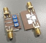
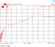
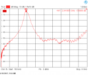
I have made some ustrip / stepped impedance filters on FR4; that work
quite good if the capacitive ends are substituted by capacitors. The high-
current sections are less impressed by the board material.
The combline result is not from the filter with the silly plastic caps.
Thats from a filter with resonator width 3 times as wide and fixed caps.
The stepped impedance filter took a lot of electromagnetics simulation
time, but the real thing is quite close to the simulation. That was for
a downconverter to receive Amsat Oscar40, but AO40 never worked.
---
This is my list of interesting frequencies, multiples of 80/100 MHz, so that the
f-multiplication does not drive the phase noise too high:
- cut/paste-
160 MHz RFM SF1611A 10 db loss
200 MHz Oscilent 811-SL200.0M-05 12 dB loss
250 MHz
300 MHz
320 MHz
400 MHz B3742 (EPCOS, now TDK) Altium ok
480 MHz B800
500 MHz B3688
600 MHz
640 MHz RFM RP1105
800 MHz
900 MHz B9431, B3588
1000 MHz
1200 MHz B1665, only 0 dBm in, Altium ok
1250 MHz B1645
1280 MHz B1641 (wuerde auch gehen, egal was davor ist)
1600 MHz B3529, Tayo Yuden F6QA1G582HJM
1800 MHz
2400 MHz B9430 Altium ok
> The best 100 MHz VCXO currently is the Crystek CVSS 945 - 100
Yes, quite good for 3.3V and probably an inductorless design.
I have a few of them here.
I got an offer from Pascall for a really good one, but they wanted
€3500+ for one. I'll use Crystec for proof of concept and will
then switch to a design of my own, based on Driscoll.
> a lumped element or microstrip filter at 1.2 GHz if you are only building
> a few units. Part and PC board variation would make testing and possible
> tuning necessary unless your PCB was manufactured with tight tolerances
> on a good substrate.
I have made some ustrip / stepped impedance filters on FR4; that work
quite good if the capacitive ends are substituted by capacitors. The high-
current sections are less impressed by the board material.
The combline result is not from the filter with the silly plastic caps.
Thats from a filter with resonator width 3 times as wide and fixed caps.
The stepped impedance filter took a lot of electromagnetics simulation
time, but the real thing is quite close to the simulation. That was for
a downconverter to receive Amsat Oscar40, but AO40 never worked.
---
This is my list of interesting frequencies, multiples of 80/100 MHz, so that the
f-multiplication does not drive the phase noise too high:
- cut/paste-
160 MHz RFM SF1611A 10 db loss
200 MHz Oscilent 811-SL200.0M-05 12 dB loss
250 MHz
300 MHz
320 MHz
400 MHz B3742 (EPCOS, now TDK) Altium ok
480 MHz B800
500 MHz B3688
600 MHz
640 MHz RFM RP1105
800 MHz
900 MHz B9431, B3588
1000 MHz
1200 MHz B1665, only 0 dBm in, Altium ok
1250 MHz B1645
1280 MHz B1641 (wuerde auch gehen, egal was davor ist)
1600 MHz B3529, Tayo Yuden F6QA1G582HJM
1800 MHz
2400 MHz B9430 Altium ok
> The best 100 MHz VCXO currently is the Crystek CVSS 945 - 100
Yes, quite good for 3.3V and probably an inductorless design.
I have a few of them here.
I got an offer from Pascall for a really good one, but they wanted
€3500+ for one.
I'll use Crystec for proof of concept and willthen switch to a design of my own, based on Driscoll.
Attachments
I would like to do an up converter, but the only non HF filter I could find in my junk box was a 60 KHz wide McCoy centered at 30.100 MHz - I don't see that as being any more useful than 9 or 10 MHz.
Win W5JAG
But still you can do upconversion from DC to 10m. Maybe you need a trap for 30.1
in the preselector.
I have a Workrite RF Woodwelder with 4 huge 810 tubes. I got zapped just once, took ages for the hole in my finger to heal.Many times I was burned my fingers with the RF at the top cap of my 6DQ6 (2X) modulated at screen by a 6V6, when I bring close when the set powered on and PTT'ed. Or place the hand near the Pi tank.
I got zapped just once, took ages for the hole in my finger to heal.
Back in the 60's and early 70's all ship to shore radio communications was AM on a frequency around 2 MHz (2.182 MHz was the emergency frequency). Marine radios ran anywhere from 50 to 300 watts and required a long wire antenna. The sailboat I was on back then had a Simpson 80 watt radio that used a pair of TV sweep tubes. The antenna was the backstay, a stainless steel wire about 1/4 inch in diameter that also served to support the mast. Since the antenna was too short to be a 1/4 wavelength, the radio had an internal loading coil to match the antenna to the radio. We had just come up from a diving trip and I was cleaning a fish with a diving knife and leaning against the backstay when one of the rookies decided that it would be a good joke to go down below and key the transmitter. Coincidentally, it was his diving knife that is probably still orbiting the planet in LEO.
RF at that frequency delivers both a burn and an electric shock. The shock induced convulsion launched the diving knife, but the burn left a stripe up my back that would take about 2 years to fully heal.
I guess I need to start looking on Ebay for some DDS / Synthesizer boards.
If these are anything like the Chinese class D audio boards they may be anywhere from somewhat useful to junk. My PLL board arrived yesterday, but I didn't have time to open the package. I spent the day outside with a chainsaw cleaning up the mess from the last storm. More rain expected today. As with the class D stuff, these appear to be a loosely interpreted copy of the company's EVB with absolutely zero documentation. The AD9910 board showed up Monday. It will take some reverse engineering to figure out how to hook it up, and some Arduino code to program it. On the plus side the board with AD9910 chip costs less than a new chip alone from Digikey. I hope it's a genuine DDS chip.
Filters. Problematic these days for those of us in the shallow end of the pool. I would like to do an up converter
The filters in a receiver serve several purposes. In a typical superhet the front end filters (before the first mixer) serve to suppress the 1st image response, and possibly reduce, by bandlimiting, the total RF power hitting the mixer. With a low IF frequency the image response limits the width of the front end filter, and an IF frequency like 455 KHz (assuming single conversion) means using a tunable filter, or breaking up large bands like 10M into chunks.
Up conversion makes the 1st image response a non issue such that the LPF in the TX is sufficient filtering.
The filter after the 1st mixer (often called a roofing filter by hams, but by nobody else in the RF world) serves to limit the total RF power seen by the receiver's IF circuitry, or data converters. Ideally this filter should be just wide enough to allow only the desired signal to pass.
When we did mission critical two way radios for police fire and military, this is exactly what we did. The front end filter allowed the desired frequency band to pass, say 450 to 470 MHz, then the crystal filter after the mixer allowed one RX channel to pass, typically a 25 KHz wide channel, though 12.5 KHz channels were also used.
The typical IF frequency for VHF and UHF radios was 45 MHz. These crystal filters are still available for a reasonable price, although the leaded through hole parts have become scarce. I have some through hole parts I got from Digikey several years ago. That's what I intend to use for the IF filter in an up conversion HF rig.
ECS-75SMF45A7.5B ECS Inc. | Filters | DigiKey
ECS-45K20A ECS | Mouser
The 7.5 KHz filter is suitable for AM, SSB, and possibly CW under good conditions. If using a data converter back end, the converters and associated circuitry must have enough dynamic range to resolve that weak signal amongst the sum total of everything else hitting the converter.
Several years ago there was a new SDR on the market that attempted to sample 1.6 MHz through 30 MHz in a fast A/D converter and then sort it all out in software. This may have worked OK in an RF environment where there were no strong signals, but with maybe 70 dB of dynamic range (10 to 12 bit converters) anything about 60 dB less than the sum total of ALL the signals present at the radio's input would be lost (most signals require about 10 dB S/N to be recovered). Shortly after that radio was released the companion switched filter bank came out.
Modern SDR's that use a computer's sound card, or other "audiophile quality" 24 bit 96 or 192 KHz A/D converters are capable of about 100 to 105 dB of dynamic range if PERFECTLY wired and configured, regardless of what the sound card claims. This can allow good operation on all modes with a 7.5 to 30 KHz crystal filter.
Good ham radios incorporate a very narrow filter for CW only use. On a contest day the CW portion of a ham band can become very crowded. There can be enough strong signals falling within the 7.5 to 30 KHz bandwidth to render that rare DX signal unheard amongst all the local hams tossing kilowatts into the air even with 100 dB of dynamic range.
A much narrower CW only filter in the 200 Hz range will help reduce the total signal power into the converters allowing a bit more range for weak signals. Such a filter can often be made by cascading several cheap crystals into a "ladder filter" but my experiments haven't proved successful even with a network analyzer to tune it.
Narrow crystal filters are usually in the 8 to 10 MHz range, while narrow ceramic filters are usually around 455 KHz, either way a second (or third) conversion is necessary. 200 to 300 Hz crystal filters are not usually cheap, but you could always roll the dice on a Chinese clone copy.....
250Hz CW Crystal Filter for Elecraft K3 with 8 crystals | eBay
Last edited:
While chasing down some SDR links I discovered a couple of neat chips from TI that may make short range wireless data devices much easier to design and build.
The TI CC1111 is a wireless transceiver with an 8051 core, USB, I2S, GPIO and 3 different license free RF bands.
The TI CC2511 is the same chip with a single 2.4 GHz transceiver.
Pre built dongles exist using each chip, but are priced beyond the "something to play with" category (over $100)
Great Scott Gadgets - YARD Stick One
Thanks for that link - Mouser had one of the 45 MHz through hole parts left; I have "blown" through all my 10M45 and a few other bits, so parts and filter are on its way to W5JAG.
I dug out my synthesizer last night, and fired it up for the first time in at least a decade, and it came up and was rock solid at 25.0000 MHz for hours with the output of the a/c blowing directly across it. It is good for a single band; right now it is set up for 20 meters with a 10.7 MHz first IF, but can be put about anywhere, or, I suppose, mixed to about anywhere.
Also about a decade ago, I bought one of these DDS kits:
Hagerty Radio Company
and, best as I recall, had it generating a fixed 10 MHz output. I have the rotary encoder and display somewhere, to finish it, I just have to find them .... I believe the one I have is an earlier version of the one he is offering now.
I have been searching high and low, and tearing my shack apart, looking for a prefab FM tuner, so I've been running across stuff I haven't seen in decades ....
Win W5JAG
so parts and filter are on its way to W5JAG
I noticed that there was 1 left last night and 0 left this afternoon.
There are several DDS boards using the AD9854 chip from China on Ebay starting at about $40.
The AD9854 is the same chip that Flex Radio used in the original Flex 1000. Years ago I DIYed my own Flex 1000. The total parts cost was about $100 and the software was freely downloadable on their web site. I laid out a board in Mentor Grapics and had it made at work.....I don't know what happened to it, but in theory it should be in a box here somewhere, along with some extra boards.
But still you can do upconversion from DC to 10m. Maybe you need a trap for 30.1 in the preselector.
Hi, Gerhard.
I've thought about that. Given my existing LO situation, it might be the better choice. Some of the mixing products look problematic at 30.1 ( I haven't looked at 45 ). Either way 30.1 or 45, I'm going to wind up with at least two mixers and oscillators to get to a frequency where I have selective filters, which violates the ( once ) cardinal rule that selectivity should be as close to the antenna as possible.
Given my ( lack of ) technical skills, single conversion to a 9 or 10 MHz IF where I have selective filters available, might be the best choice for me. From there, I could make another mix down to 455 KHz and get passband tuning. edit: Then, if I can find that 455 KHz ceramic filter I pulled from my FT-847, I can tail end the IF strip with that filter to get rid of any wideband noise that crept in.
As the great philosopher Dirty Harry Callahan once said: " A man's got to know his limitations".
Win W5JAG
Last edited:
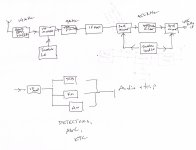
I'm thinking something like this is actually do-able ( for me ).
Additional bands could be added with the correct bandpass filter, diode switching, and changing the first LO frequency. Transmitter blocks wouldn't be hard to add in, as long as some allowance was made for T/R switching the common blocks while the RX strip is being built out.
Win W5AJG
Additional bands could be added with the correct bandpass filter, diode switching, and changing the first LO frequency. Transmitter blocks wouldn't be hard to add in, as long as some allowance was made for T/R switching the common blocks while the RX strip is being built out.
Win W5AJG
Attachments
I turned on my PC to check my email, then came here. As I opened this page the usual targeted advert appeared on the to. Sometimes that are way off......sometimes they are tapped directly into my brain. This time the advert is for a 45 MHz crystal filter. As I opened the reply box to type this reply the advert is for a Tektronix TTR500 Vector Network Analyzer, maybe they can tap my brain but they obviously can't see my bank account. Tek's "low cost VNA" costs $9000.
That rule comes from a day before good filters were cheap, intermodulation products were a bigger problem than they are now, and LO sideband noise was a limiting factor in CW reception. Up conversion radios are now pretty common. The area around 45 MHz seems to be the common choice for HF. You apply lumped element or tunable LC filters at the antenna, with a HPF at about 1.6 MHz unless you have no AM broadcast stations nearby, on HF just to reduce the total power into the mixer. Then upconvert to 45 MHz where you gain some filtering in the crystal. You can then convert directly to 455 KHz, or to 9 MHz for CW (cheap filters) and 10.7 MHz for SSB (again cheap filters) By moving the two LO's with respect to each other you can use the filter skirts for a variable width passband.
There is a simple solution for the LO, the Si570 programmable oscillator as used in the Softrock SDR, but they are not cheap. I will try the Chinese PLL's first. The $20 board that showed up yesterday looks good, but I haven't fired it up yet.
I've thought about that. Given my existing LO situation, it might be the better choice.....violates the ( once ) cardinal rule that selectivity should be as close to the antenna
That rule comes from a day before good filters were cheap, intermodulation products were a bigger problem than they are now, and LO sideband noise was a limiting factor in CW reception. Up conversion radios are now pretty common. The area around 45 MHz seems to be the common choice for HF. You apply lumped element or tunable LC filters at the antenna, with a HPF at about 1.6 MHz unless you have no AM broadcast stations nearby, on HF just to reduce the total power into the mixer. Then upconvert to 45 MHz where you gain some filtering in the crystal. You can then convert directly to 455 KHz, or to 9 MHz for CW (cheap filters) and 10.7 MHz for SSB (again cheap filters) By moving the two LO's with respect to each other you can use the filter skirts for a variable width passband.
There is a simple solution for the LO, the Si570 programmable oscillator as used in the Softrock SDR, but they are not cheap. I will try the Chinese PLL's first. The $20 board that showed up yesterday looks good, but I haven't fired it up yet.
Attachments
Hi, Win,
remember that at least the first mixer must be terminated in 50 Ohm wideband, which
is essential for keeping a high intercept point. This will probably be a ring mixer, there
are not much alternatives.
Use high side injection as at least the harmonics don't cross the input bands;
large scale harmonics are generated by the switching action of the diodes in
the mixer. It does not pay to invest much into a nice oscillator sine wave.
Ring mixers are perfectly happy when fed with square waves. They are
switches, after all.
A friend of mine had excellent results with a variable gain amplifier from Analog Devices
as regulated IF.
I do not like too narrow IF filters, they ring and make me feel blindfolded.
They also have huge group delay, that comes with the necessary Q.
If you have an AGCed stage in front of the filter, there will be a lot of pumping
effects and motor-boating like oscillation.
There have been a lot of good designs in QEX, which are easily accessible.
There are also the books of Ulrich Rohde, but they cost an arm and a leg.
You've got to ask yourself one question: Do I feel lucky?
Gerhard
remember that at least the first mixer must be terminated in 50 Ohm wideband, which
is essential for keeping a high intercept point. This will probably be a ring mixer, there
are not much alternatives.
Use high side injection as at least the harmonics don't cross the input bands;
large scale harmonics are generated by the switching action of the diodes in
the mixer. It does not pay to invest much into a nice oscillator sine wave.
Ring mixers are perfectly happy when fed with square waves. They are
switches, after all.
A friend of mine had excellent results with a variable gain amplifier from Analog Devices
as regulated IF.
I do not like too narrow IF filters, they ring and make me feel blindfolded.
They also have huge group delay, that comes with the necessary Q.
If you have an AGCed stage in front of the filter, there will be a lot of pumping
effects and motor-boating like oscillation.
There have been a lot of good designs in QEX, which are easily accessible.
There are also the books of Ulrich Rohde, but they cost an arm and a leg.
You've got to ask yourself one question: Do I feel lucky?
GerhardYou've got to ask yourself one question: Do I feel lucky?
A little.
Maybe.
No, not really.
I can't do high side injection to a low VHF IF without a new LO, or mixing my existing one up, which creates more harmonic products to try to work through or around.
I was trying to work out some of the harmonic distortion products in my head the other day while mowing some property I have, and low side injection to 30.1 didn't seem attractive.
A search of the parts bins turned up one (1) Mini Circuits SBL-1; a few dozen MBD101 diodes, and a handful of 5082-2835 diodes. Enough of the 5082 types to make a couple of mixers. I didn't look for ferrite cores, but I'm sure I have some.
No sign of my DDS yet, though.
I had contemplated using active mixers, because I'm already familiar with them, and it reduces the number of blocks that have to be built.
I have ( and read - about thirty years ago ) Single Sideband Systems and Circuits, first edition, edited by Sabin and Schoenike, which was Collins Radio follow up to Single Sideband Principles and Circuits. I am nearly positive I have one of Rohde's books on receiver design at the office, but it would be about the same vintage as Systems and Circuits. I have not read it.
Interestingly, at p. 98 of the Collins book, there is discussion of up conversion IF's, which offer cost advantages because of widespread use in other services, and those frequencies suggested were 45 MHz, 70 MHz, and 75 MHz.
One thing is for sure - projects like this are always a big learning curve, and help one appreciate the difficulty of bringing complex products to market.
Reworking my original very simple rig, about 90% of which still exists, and using it as a tunable IF - my original plan - is starting to look better, as well as just building out a DZ Sienna, which is sitting in a box in the back of my office.
George, I looked at Surplus Sales of Nebraska, and they have new surplus 45 MHz 4 pole filters for about $15, but they are 30 KHz wide. Do you have a link to the PLL you are getting ready to work with?
Win W5JAG
building out a DZ Sienna, which is sitting in a box in the back of my office.
I met Brian (W0DZ) at the Orlando hamfest at least 10 years ago when he had a mostly finished prototype and a dream. The electronics industry was beginning to recover from a major downturn and parts were in short supply. It didn't matter if you were an ex HP / Agilent engineer trying to launch a ham radio kit or Motorola with a huge procurement staff......nobody could get commodity parts like small audio amps or LDO regulator chips. 26 to 52 week lead times were quoted for half of the Digikey catalog.
We sat around and talked for about an hour (his booth was next to ESRC) and went over his radio design. I don't remember the details now, but I came away thinking that it was an excellent design. Maybe that is your safest path to success, especially since you already paid for it!
Do you have a link to the PLL you are getting ready to work with?
I got one of these because it was cheap, and stocked in the US. It showed up in about 3 days. The same board is available cheaper if you don't mind waiting for a slow boat to bring it from China.
35M-4.4GHz PLL RF Signal Source Frequency Synthesizer ADF4351 Development Board | eBay
The ADF4531 chip is not a state of the art chip, but it is much better than a lot of what's out there, especially in it's price range. The state of the art TI chip that I want to use is $60 just for the chip and it's an LGA SMD part. The first "L" stands for leadless, which makes them nearly impossible to hand solder, especially on a home made PC board.
I also got a board like this one. The version I have is a bit different and no longer available. The AD9910 chip requires a 1 GHZ clock. Multiplying a good 100 MHz clock by 10 is the best way to make this. These boards use an internal PLL to create 1 GHZ from a 40 MHz crystal. That is usually far too noisy. But I will know when I test it.
AD9910 DDS module 420M 1MSPS highest output sampling frequency signal generator | eBay
This will probably be a ring mixer, there are not much alternatives.
A ring mixer is the hot ticket, but they don't have to be made with diodes. Fet mixers have become the first choice recently. For HF a fet mixer can be made with analog switch IC's.
Ring mixers are perfectly happy when fed with square waves.
Pure square waves are good at HF. Diodes and fets have a slower turn off than turn on time due to charge storage effects. At VHF and above this can result in a period of time when all the diodes are conducting during transition. It is better to use square waves with a bit of dead time as is done with H bridges and SMPS designs. Improvements in IP2, IP3 and conversion loss were noted during testing.
- Home
- Member Areas
- The Lounge
- No RF gear here?