Been pretty busy lately, and when I've had time to work on this, I've had motivation deficit disorder.
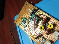
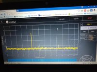
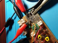
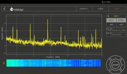
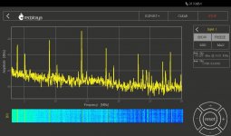
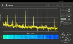
I got some of those 23.4 MHz EPCOS SAW filters, and removed the existing input attenuator, and put the SAW filter in its place.
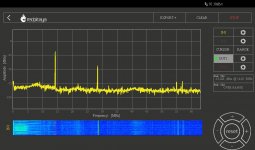
According to the RP, it looks like it has about 8 dB insertion loss, so it will be about right for the DDS LO. For some reason, I did not check the passband width or slope of the skirts.
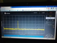
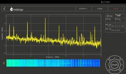
I think the spectrum pics are at the input to the SAW filter, and the last pic is the output.
edit: in these pics, the RP is generating the test signal - the DDS is at home ...
I got some of those 23.4 MHz EPCOS SAW filters, and removed the existing input attenuator, and put the SAW filter in its place.
According to the RP, it looks like it has about 8 dB insertion loss, so it will be about right for the DDS LO. For some reason, I did not check the passband width or slope of the skirts.
I think the spectrum pics are at the input to the SAW filter, and the last pic is the output.
edit: in these pics, the RP is generating the test signal - the DDS is at home ...
Attachments
Last edited:
I was in the ham shack this morning, and flipped on the cheap DDS board, and ... nothing. I had to turn the volts up to about 10.5 from the normal 8 to bring it to life.
Not sure what is up with that, but the obvious suspect is temperature sensitivity - it's been in the 30's F overnight - much warmer in the shack since it's well insulated, but still considerably below normal room temp. In mobile service around here, the radio, if ever finished, will routinely see temperatures ranging from below zero F, to more than 100F, so, this looks problematic, but I guess it is best to learn this sooner, rather than later.
The Si5351 frequency synthesizer is in a drawer here at the office, so when I get a chance I may leave it outside overnight to see if it has the same issues. Hopefully this is just a cold display issue, and won't be that big an issue since the control head will be in the passenger compartment.
Mouser has Infineon dual gate mosfets really cheap right now, they are marked not recommended for new design, so are on their way out. There is a really good price break at 100 parts - I got 100 BF998 (12 Vds) for $18.60 U.S. 100 BF2040 (7 Vds) would be less than $15 bucks U.S, but I did not order any of those. No further price break on either until you get 1000 pieces. I like the NXP BF992 best because of it's higher Vds, but it is considerably more expensive. And I'm cheap.
And, there are now SMD crystals for conversion from 45 MHz to 455 KHz in their catalog for about a buck each. I picked up a couple of those.
Not sure what is up with that, but the obvious suspect is temperature sensitivity - it's been in the 30's F overnight - much warmer in the shack since it's well insulated, but still considerably below normal room temp. In mobile service around here, the radio, if ever finished, will routinely see temperatures ranging from below zero F, to more than 100F, so, this looks problematic, but I guess it is best to learn this sooner, rather than later.
The Si5351 frequency synthesizer is in a drawer here at the office, so when I get a chance I may leave it outside overnight to see if it has the same issues. Hopefully this is just a cold display issue, and won't be that big an issue since the control head will be in the passenger compartment.
... a single gate low-noise mosfet of which I bought ~100, enough for life. ...
Mouser has Infineon dual gate mosfets really cheap right now, they are marked not recommended for new design, so are on their way out. There is a really good price break at 100 parts - I got 100 BF998 (12 Vds) for $18.60 U.S. 100 BF2040 (7 Vds) would be less than $15 bucks U.S, but I did not order any of those. No further price break on either until you get 1000 pieces. I like the NXP BF992 best because of it's higher Vds, but it is considerably more expensive. And I'm cheap.
And, there are now SMD crystals for conversion from 45 MHz to 455 KHz in their catalog for about a buck each. I picked up a couple of those.
I worked on it yesterday, with the intention of getting the new board mounted in the chassis where I could see how the RX would work, but a handful of SNAFU's thwarted that.
I've been waffling on whether or not I wanted the LO filtering / attenuation on the new board, and I finally decided to put it on the board that will handle the T/R switching and other housekeeping, so I removed all that stuff.
I got the TX mixer locking connectors installed, and was killing some time playing with output filters, when the TX SA602 just died. I replaced it, and the replacement also died instantly. The culprit was a bad 78L05 regulator at the power pin, but it cost me two SA602 before I figured this out. The regulator was from a bag of about a hundred that I got for some insanely low price at a hamfest, so I should have had better sense than to use them, but other than being all over the place in voltage ( I've seen anywhere from 4.9 to 5.4 VDC ) they haven't given me any trouble. This one had burned in for about a half hour before I trusted it, and was outputting a steady 5.2 volts at up to 16 volts in, to simulate what my alternator can put out.
Naturally I replaced it with another one from the same bag, burned it in overnight, and it is spot on at 5.0 VDC. To hedge my bets, I replaced the SA602 with one from a strip obtained cheap via Bay from China.
The pic is the eBay '602 going through burn in on the RP. I stated before I could not tell much, or any, difference, between these dubious '602, and genuine '602 and that is still true. The second pic is my notes on this chip, measured by the RP. The LO is suppressed 38 dB at the output, and the IF is suppressed 27 dB, with the inputs and outputs being single ended. I think I am going to use a 3 dB pad between the output of the SG-9 and the transverter board.
I haven't seen any enclosures that look suitable for a control head, so I got a giant 500mm x 500mm x 500mm 3D printer to possibly DIY one. I have no idea what the learning curve for that thing will be - the unopened box is sitting in the back office under the DZ Sienna kit.
Attachments
Last edited:
This is a dual gate MOSFET (BF998) broadband amp following the TX mixer.
I'm using the RP to feed it the -27dBm that I expect from the mixer, the drain load is a 47 ohm resistor for a 50 ohm output; I'm getting -18 dBm or about 9 dB of gain, pretty much flat out to 50 MHz ( as high as the RP goes ).
Is this about the right amount of gain given the low drain load, or do I need to do some tweaking on it?
I burned out the last of my MMIC's last night - just could not make them stable. I suspect they all died from self oscillation, which when combined with the desired signal, exceeded the max power. I couldn't see where they were oscillating, but they were acting wonky, consistent with a VHF oscillation.
On the plus side, I've gotten pretty good at being able to rework these proto boards without damaging them.
Attachments
I changed the bias on the control gate by adding a couple of volts, putting it at about 3.75 VDC g2s, and dropped the source resistance down to 100R ( 0.41 VDC ), and this more than doubled the output from the untuned amp.
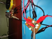
Here is the whole smack strung together, with the RP as the signal source, eBay SA602, and the Infineon BF998 DG MOSFET.
I can push the output up over 0 dBm if I want, but it is yet to be bandpass filtered, so I'm not sure I want it too strong. The bandpass filter will go on the board for the TX strip.
This board is going to go in service in the chassis, so I can start testing the receiver in the car.
Attachments
That gradually descending high noise floor was bugging me, so I stayed in the office at lunch and played with it a bit.
It's not related to the input drive levels.
It does seem related to matching between the SA602 and the BF998. Best I recall, the output load of the SA602 is about 4K. I had a pretty high value R on gate 1, so I dropped it to 2200R since I am taking the output from the '602 single ended.
This made a 10 dB improvement in the noise floor above about 5 MHz.
I think there is still a lot of power and gain left on the table; the 100 ohm source resistance could probably be reduced a lot, maybe by a factor of 10.
Attachments
I swapped the Infineon BF998 out for a NXP BF992. The bias is not quite right for the BF992, but it looks a bit better, I think. Hard to tell. I'm probably done here.
The receive RF amp is also a BF992, so it makes the board a bit easier to install since I don't have to worry about protecting the lower Vds of the BF998.
The receive RF amp is also a BF992, so it makes the board a bit easier to install since I don't have to worry about protecting the lower Vds of the BF998.
Attachments
Last edited:
Correct part number? ADF4351 maybe?ADF451 VCO
I had forgotten all about the ARRL's experimenters publication. I Googled the table of contents and didn't find a clue to what I assumed was an Analog Devices RF synth chip.
I did see the name of an old friend who left Motorola long ago. Kai Siwiak KE4PT and I made possibly the first legal two way amateur contact on the then new 902 MHz amateur radio band early in the morning EST on the day the band was opened to amateurs sometime in the mid 80's.
I had made a pair of hacked Motorola STX police walkie talkies that worked on the bottom end of that band. Later in the year I got on the roof of my house with one of them while everyone present at the Motorola Amateur Radio Club's field day operation in a county park a few miles from my house passed the other radio around to rack up contacts on that band.
I built a repeater for 902 a few months later, but it would be vaporized by lightning after only a few months of operation.
Jack, I have not - when the economy tailslid into a depression around here, if an expense was non essential to staying in business, I just let it go ... that included all my hobby stuff. This is why I'm so far behind on stuff like H mode mixers, Tayloe detectors, SMD /SMT, etc.
Times are better now, sort of, but I haven't re-upped my ARRL yet, been meaning to ....
I'm headed to northwest Arkansas this afternoon, where the bookstores are better, and I'll try to find it on a newsstand. Thanks for the tip.
While I've got you guys here ... Inductors and band pass filters ... I've got some SMD inductors now, some look like real inductors made with tiny coils of wire, some look like any other smd component - i.e. no clue about what is inside. Will SMD coils be too inefficient at HF to use in a 50 ohm band pass filter at a power level around 0 dBm to maybe - 10dBm? Or should I just wind some toroids or use regular inductors with the color band conformal coating? I have all of them available, as well as those slug tuned coils I used on the experiment board. But they're really big.
Correct part number? ADF4351 maybe?
My transpositional error!
Never reached that high into the ether although I had one of those 0.25m transponders purchased for almost nothing at a Parma OH Hamfest. Most of the time 6m and 2m, CW on 40m and 20m
Most of my ham radio experimentation was at 432 MHz and above. In a time long ago there was an ATV repeater on one of Miami's TV towers at the 300 foot level or so. I had a PC electronics ATV transmitter and a DIY 40 watt linear RF amp. I still have the amp. Cameras for NTSC TV were expensive then, so We hooked up the video output from out Apple II clones and "texted" to each other.....there might have been some game playing too. This was obviously before the internet or the IBM PC existed....late 70's I think.
FP&L's gigavolt transmission lines ran along the canal across the street from me. On a damp summer night the broad band RF noise from them made HF useless up to 10 MHz or so. Even on 20 meters the S meter hung out near S9.
I still have a 1296 MHz walkie talkie in a box around here somewhere. I was on a mission to break the 902 MHz QSO distance record in the 1990's but the city made my dish go away and AT&T planted a powerful LTE cell tower across the street from me. Still have the kilowatt level power amps, but my current QTH is down in a "holler" with 200 to 300 foot hills on all sides, so VHF and above is useless unless I go mobile.
I did make a few short range QSO's on 10 GHz many years ago using microwave door openers and parabolic reflectors.
At the current time I have not yet put up an antenna, but all the wire and coax is sitting here on the basement floor just waiting.....
This is a genuine SA602. Compared to the eBay '602 under identical conditions, it looks to me like the genuine chip has:
marginally less spurious response;
marginally lower noise floor;
marginally less output (3 B)
marginally better suppression of the 9 MHz IF signal ( about 3 db); and
way, way, worse suppression of the LO signal - the other chip was 20 dB better.
I don't know what manufacturing tolerances are, but everything except the LO suppression could be normal manufacturing variance. I don't know what's up with the bad LO number.
HF is probably not much of a test. The eBay chip might, or might not, be useful at VHF.
Attachments
I was in the ham shack this morning, and flipped on the cheap DDS board, and ... nothing. I had to turn the volts up to about 10.5 from the normal 8 to bring it to life.
Not sure what is up with that, but the obvious suspect is temperature sensitivity - it's been in the 30's F overnight - much warmer in the shack since it's well insulated, but still considerably below normal room temp. In mobile service around here, the radio, if ever finished, will routinely see temperatures ranging from below zero F, to more than 100F, so, this looks problematic, but I guess it is best to learn this sooner, rather than later.
The Si5351 frequency synthesizer is in a drawer here at the office, so when I get a chance I may leave it outside overnight to see if it has the same issues. Hopefully this is just a cold display issue, and won't be that big an issue since the control head will be in the passenger compartment.
Mouser has Infineon dual gate mosfets really cheap right now, they are marked not recommended for new design, so are on their way out. There is a really good price break at 100 parts - I got 100 BF998 (12 Vds) for $18.60 U.S. 100 BF2040 (7 Vds) would be less than $15 bucks U.S, but I did not order any of those. No further price break on either until you get 1000 pieces. I like the NXP BF992 best because of it's higher Vds, but it is considerably more expensive. And I'm cheap.
And, there are now SMD crystals for conversion from 45 MHz to 455 KHz in their catalog for about a buck each. I picked up a couple of those.
I already bought enough BF988 to last a lifetime. The BF982 is a double BF981 (same issue with the smd (9) series). I also have a fair share of those 45 MHz xtal filters (2 and 4 pole), with the xtals for conversion to 455 KHz. For the LO I had developed a solution without any spurs. A rock-stable VFO from 32 to ~32.7 MHz with binary divider to 1,000... 1,022 KHz. This was filtered and used as reference for the VCO, to provide a range from 45...75 MHz via programmable divider. Digital phase detector for fast lock-in and analog phase detector for very low noise. I even got DOD clearance for a Vari-L current controlled inductance used in the VCO... Noise blanker after a 2-pole 45 MHz filter but instead of switches in the signal path, a switch in the path of the 2nd LO, greatly improving the blanking effect.
Me too, also in Melbourne. Mostly June- September 1974. What was your handle? Which suburb approximately?My past experience in the field was in the mid 70's as a ratbag on 27MHz band,
... I don't know what's up with the bad LO number. ...
Apparently, dodgy soldering. When I swapped out the chips, I just set the new one with the hot air gun. I came back and touched up the pins with an iron and bit of fresh solder, and that brought the LO rejection back to normal.
Didn't change anything else.
Started the tansmitter board.
Instead of the IF transformer type coils used in the bandpass filter on the test board, I wanted to use toroids. Unfortunately, the toroids in my travel box were bigger than I wanted to use ( T-50 ), and the magnet wire I had with me was way too small (0.1mm), and the combination of the two was just a disaster. Try to wind the coil tight, and the wire would break. Stick the end in a flame to burn off the enamel, and the wire would melt (!). Tension the wire to hold the coil tight to the board, and it would break.
After a morning of struggling with that, and winding up with a filter with coils so jiggly and mobile that I doubt it would have survived the trip home in my toolbox, much less pounding around in the trunk of a car, I just gave up and completely disaasembled it.
The other inductors I had on hand were some 6 uH ish slug tuned coils, a bit on the large side, 1206 and 0805 smd/smt inductors, and some 1/4 watt size molded inductors. I wanted to use the SMD devices, but I wound up using the molded inductors.
I made a mistake right from the start, but didn't realize it until later, and I still don't completely understand it.
To make it simple, I decided I decided I woud use a link coupling in and out of the filter; I wanted a good signal transfer, so I wound the link the pinched length of the inductor, about four turns. When I tested the first pole, the resonant frequency was way too high - it took about 56 pF of additional padding to bring it down to twenty meters. I wound the second inductor the same way, and got precisely the same result.
The resulting filter does have a bandpass response, but the slopes are shallower than I expected - about -25 dB at 10 MHz, and maybe -20 dB at about 19 MHz. After thinking about it a while, my WAG is that I managed to create a significant parallel inductance on the same core, large enough to significantly lower the inductance and requiring the extra capacity to resonate where I wanted it. I'm aware of Q, won't pretend I understand it, and doubt these were high Q coils to start with, and my parallel inductor probably doesn't help the Q.
That said, it's probably ( barely ) good enough, and on the plus side, is quite compact and very rigid. It won't fail banging around in a car. I might add a third pole and see what, if any, that adds to the skirts.
Attachments
Last edited:
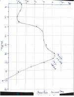
This was bugging me, so, I took it apart and replaced the four turn link coupling with a two turn link coupling, which fixed the odd behavior with the resonant points.
But the bandpass response is still somewhat unsatisfactory. A crude graph of the response is attached.
The high side response looks good, the low side okay, but it has a pretty good bump on the top, right at the resonant point of the poles. The bump looks like it could be a tuning error in the filter poles, but I've played with it some, and so far can't seem to tune it out, although I can probably improve on it a bit, given more time. I'm glad to have the Red Pitaya, but using it for this kind of filter tuning is pretty tedious.
Or, I wonder if this is an issue of coupling between the two filter poles. They're top coupled with a fixed 7 pF ceramic capacitor. I thought about putting a trimer here when I was building it, but really didn't want to sort through three variables tuning it. I can put one there, but would have to rebuild it again.
Attachments
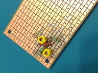
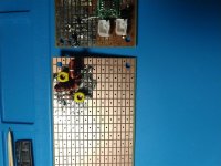
I replaced the transformers previously made with the molded inductors, with some wound on T-37-6 toroid cores.
The latter are much more efficient - looks like the insertion loss of the whole filter is maybe only a couple of dB, maybe even less than that.
I haven't played much with the filter; I did spend some time looking at just the first tuned circuit, and was somewhat surprised at how selective a single tuned circuit can be when made with a good quality inductor.
Attachments
- Home
- Member Areas
- The Lounge
- No RF gear here?