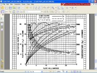
Are you saying that the dissipation limit curve is outside the linear zone??????
not a question of linearity, the first rule afaik working with tubes, never operate a tube outside those curves(plate dissipation limits), it is a guaranteed way to kill your tube...
I'm not sure if by 'electron cloud' you mean space charge. If so, it was not the reason for inventing the tetrode/pentode. The tetrode gives more gain, especially at higher frequencies, by shielding the potential on the anode from the electron stream.
In a triode, the electron cloud/space charge reduces the number of electrons arriving at the anode and thus the current is reduced, then the gain is also reduced.
If we add another grid, the electron cloud extends to a greater space region, the density of the electron cloud is smaller, then its effects are also reduced, increasing the number of electrons reaching the anode, increasing the current, and increasing the gain, we now have a tetrode.
If we now add another grid, the above reasoning is still valid, then again, we increase the gain, we now have a pentode.
Not all electrons reach the anode are absorbed, some are re-emitted to the cathode, others are retained in the cloud, others are rejected by the cloud.
This is called secondary emission.
The addition of a grid (tetrode) or two grids (pentode) may decrease secondary emission, absorbing the electrons re-emitted, further increasing the total current, and then the gain.
Note that it is very difficult to distinguish in the electron cloud, which were there and which was re-emitted by the anode.
I said it in a more crude in post #9 and #13.I know my English sucks, but so much?
He keeps wanting to reduce space charge, because he seems to think it creates. nonlinearity. I keep pointing out that space charge is a necessary part of normal valve operation. Linearity in normal triode operation is created by the grid and anode having the same 3/2 power law, due to geometry.
Not really at all, as I said in post # 36, the Child-Langmuir law or 3/2 power law derived from Poisson's equation, which in turn, derived from Maxwell's equations.
Poisson's equation can be solved in various coordinate systems, then symmetry (Geometry) changes, but remains a 3/2 power law.
Originally, one of the assumptions to derive the Child-Langmuir law was the electrodes are planar, parallel, equipotential surfaces of infinite dimensions, far from triodes we know, and its geometry.
However, we note that triodes manufacturer, used geometry and physics, to improve them.
The cylindrical symmetry allows quieter sleep.
So your personal opinion that space charge reduces valve linearity in a thermionic triode is based on a photoelectric diode experiment to measure Planck's constant? The former is based on voltage change; the latter on light frequency and intensity.
I am aware of the possibility of language problems, which is why I have given popilin the opportunity to explain his ideas so I can see where he gets his strange idea from. I suspect he is confusing emission (whether thermionic or photoelectric) with total current. In the photodiode all the electrons emitted end up at the anode.
As I said in post#32, since electrons have no conscience of their own, they do not know if they were created by the photoelectric effect, or were created by thermionic effect, then the result of Planck's constant experiment can be applied to any electron, including those of a triode.
Because the electron cloud/space charge, in a vacuum photodiode not all the emitted electrons reach the anode, then you who confuses emission with total current.
Last edited:
You still don't get it do you? If you deliberately run a valve in the region where the space charge is small then you are approaching the temperature-limited region. In this region the triode is not linear: it stops being a triode because the current depends on cathode temperature rather than electrode voltages. This is how a thermionic noise diode works.
Please go away and read up how triode valves really work. There is plenty of good stuff on the internet. I have tried to correct your misunderstanding but there is a limit to how much free tuition I can give to an obstinate student. Maybe someone else can take over. I have had enough.
As explained in post #28 and #36 I consider demonstrated that the electron cloud/space charge affects the linearity of the triode.
Moreover, the curves speak for themselves!!!
Working with triodes, most of us use the information provided by the manufacturer data sheet and work below the dissipation limit curve, which in most cases is in the linear region, as I said in post #36 and #38.
I still have not finished my thesis, you can tell me I'm just a TV repairman if you want, but your PhD degree gives you no right to insult me that way.
Fortunately I am not your student, and I suggest you study a little bit more physics, lest they repent in your university.
Last edited:
Hi Tony
Oh my God !!!, You're right, I'm a fool !!!
Possibly because of what you say curves are called dissipation limit curves !!!
you see these in some of the plate characteristic curves as dashed lines, but where this is not shown, you can always look at the plate dissipation spec.....
actual practice, the plate dissipation spec is much higher than actual operating point chosen, about 25% is typical for small plates.....
If you look at how a 12AU7 mu varies with plate voltage, the seemingly nutty idea of putting 320V across it starts making sense. I suspect the actual results won't look much like the sim- even with operation on the flatter part of mu vs Vp, there will be a lot of higher order harmonics. But if you're going to extract the most out of a tube with poor linearity, you have to take extreme measures.
Absolutely true and consistent with the physics of the triode, my knowledge is limited and your views always teach me something.
Of course, you could get better performance with a different tube and different circuit and not deal with 650V supplies, but that's not a polite thing to say.
It is also true, but what else I can do with a ECC82/12AU7, sell?
Thank you for your contribution, you are one of the few who supported me.
Attachments
I disagree strongly with your physical interpretation, but the circuit will work. At your chosen voltages and configuration, you're running roughly 3mA through the tubes with 325V on the plate. At that current and voltage, you're in no danger of over-dissipation, but you're still safely in the space charge region. The thing to watch out for is the heater-to-cathode voltage ratings- you may have to use different tubes for top and bottom and bias up the heater supply for the top tube.
And not to be facetious but, yes, if you're designing a hifi amp (as opposed to a guitar amp), you actually would do better selling the 12AU7s and getting another tube which can be used in a simpler circuit and give higher performance. Your circuit does extract better performance than usual for that tube type, but the 12AU7 is not a very linear tube to start with.
And not to be facetious but, yes, if you're designing a hifi amp (as opposed to a guitar amp), you actually would do better selling the 12AU7s and getting another tube which can be used in a simpler circuit and give higher performance. Your circuit does extract better performance than usual for that tube type, but the 12AU7 is not a very linear tube to start with.
Hi SY
Thank you for your feedback, for ECC82/12AU7, Vkf=180V, floating filament supply that voltage I will not have problems.
It is true that ECC82/12AU7 is not very linear , but from the beginning, its use was done to demonstrate that it is not so bad after all.
In real life, I would use the ECC99.
Thank you for your feedback, for ECC82/12AU7, Vkf=180V, floating filament supply that voltage I will not have problems.
It is true that ECC82/12AU7 is not very linear , but from the beginning, its use was done to demonstrate that it is not so bad after all.
In real life, I would use the ECC99.
Wrong link
You know, I just went back and looked at the link I posted...this is not the one I intended...i was wondering why all the talk of space charge tubes....i had this and another window open and copied the wrong link....now i just need to go back and find the one i intended to post....sorry bout that....
As far as the 12AU7 goes...or any tube for that matter...the non-linear operation is part of the magic of tubes IMHO, if you are looking for linear operation then you might as well just build a chip based preamp or something. Personally, I like the 12AU7 and it's nice "just that right amount" of 2nd order distortion that warms the music up.....but this is a matter of opinion and taste which is never worth disputing...
One of my favorite circuits i built some time back is over at Shine7 Audio DIY Page ....very simple, elegant design that sounds very nice...IMHO again....
I beleive you are saying both the same thing in different ways.....
http://www.fourwater.com/files/spacecharge.txt
You know, I just went back and looked at the link I posted...this is not the one I intended...i was wondering why all the talk of space charge tubes....i had this and another window open and copied the wrong link....now i just need to go back and find the one i intended to post....sorry bout that....
As far as the 12AU7 goes...or any tube for that matter...the non-linear operation is part of the magic of tubes IMHO, if you are looking for linear operation then you might as well just build a chip based preamp or something. Personally, I like the 12AU7 and it's nice "just that right amount" of 2nd order distortion that warms the music up.....but this is a matter of opinion and taste which is never worth disputing...
One of my favorite circuits i built some time back is over at Shine7 Audio DIY Page ....very simple, elegant design that sounds very nice...IMHO again....
As far as the 12AU7 goes...or any tube for that matter...the non-linear operation is part of the magic of tubes IMHO, if you are looking for linear operation then you might as well just build a chip based preamp or something.
No. It is the myth spread by Wiki page about "tube sound". Very wrong and nasty. Non-linear operation is desirable for guitar effects. For sound reproduction tubes are used exactly because they have smoother transfer characteristics than solid state devices, and allow to achieve very low level of audible distortions. You don't need "linearity" of transfer curve for minimum of distortions. You don't need strict alignment of tube electrodes with Earth magnet poles. You don't need precise shape of the bulb. All what you need, is minimum of distortions that are audible.
And tubes are exactly such devices that allow to get such good results.
Yes, when you hear less of distortions that does not mean the device is "linear". It is not necessary. What is necessary, to have non-linearities of lower order. Like, if the curve is very slowly bent it is much better than when it is straighter, but bent sharper. Straightening sharp non-linearities of solid state devices you make this curve even sharper. That means, you create more of audible distortions minimizing distortions that are less audible. Adding such distortions you are getting "dry", "dead", "lifeless" sound. "Sterile sound" does not mean absence of distrtions. That means presence of nasty high order distortions, even when they are measurable by tool as low, they hurt hearing.
Hi jmillerdoc
Thanks for your feedback, and I appreciate your support, I think you're the only one who has understood my point, which is very close to the others, but in a different language, and I do not mean my horrible English.
There is a physical and mathematical question why the 2nd order harmonics harmonics are nice (small levels), but would enter another dispute ....
Preamps you mention look very good and type of valve at the end a matter of taste.
Best regards
Johann
Last edited:
Hello,
I took the day off and stopped by for the entertainment. I am not disappointed. Sy you are a gentleman with a brain. Will the real Ph.D. please stand up?
Referring to post number 7 and “flashover”, is that a technical term? Is it defined in one of the referenced texts? There is 650 volts on the top plate at start up, the top cathode and grid have no applied voltage, neither does the bottom plate. What is to flash, the top plate to the bottom cathode or grid? Seems to be a non-arching distance to me. I see Sy’s point regarding plate voltage to heater differential as the cause for concern.
I see 2 things completely missed in the discussion plus a lot of pilling on the much maligned 12AU7. The SRPP is a Single End Push Pull circuit that can be much more linear than the sum of the two triodes. The SRPP distortion output like the cathode follower is particularly sensitive to loading.
The circuit shown does not include a load, only that 100K bleed resistor.
What happens to the simulation with the next stage of the project connected?
DT
Hi Wavebourn
How lucky that I see you around here.
Could you give me another trick to remove the magnet wire enamel?
I'm going crazy with an OPT, and I can't with 0.2mm wire.
Aspirin does not work because the enamel is polyester imide resin.
And tested with acetone, thinner, and up brake fluid !!!
Fire tends to ruin the wire, please, help me.
Best regards
Johann
Hi DualTriode
Hooray! Do not know how much I appreciate your feedback.
I thought I was alone.
Yes you are right, the circuit ist just a thought experiment to demonstrate that ECC82/12AU7 isn't the worst guy in the class.
I think the circuit is not for a great load, if you want I can make the calculations.
When I build a SRPP first fix the load, this was not the case, I'm sorry.
If my brain is still working Zout is in the order of 35 Kohm. (54K // 100K)
Best regards
Johann
Last edited:
Now that you mention it, I never thought of the dielectric strength of vacuum.
It's in the order of at least 20KV/mm, then ECC82/12AU7 must be too small or 650V can be enlarge so much due to SRPP topology.
Furthermore, the Philips handbook says Vao=550V max. each section.
I never intended to connect the circuit to another stage, but could be a grid of a valve in Class A1.
Not very useful after all, right?
Best regards
Johann
As far as the 12AU7 goes...or any tube for that matter...the non-linear operation is part of the magic of tubes IMHO, if you are looking for linear operation then you might as well just build a chip based preamp or something.
+1.
I disagree with wavebourn. SS devices don't have sharp corners in their characteristics, except when you completely run out of headroom, which is out of bounds anyway.
Triodes only have good linearity because of the inherent feedback inside the valve, between and anode grid. Take that away and you are left with a pentode, which is no better than a transistor, except a transistor has a lot more gm so you can afford to use a lot of degeneration, which gives you a compound device that is even better than a triode.
If you're truly interested in low distortion, then transistors will always win.
People who build with valves but chase ultra-low distortion with dozens of 'support' transistor are either doing it as an novel exercise , or they're hypocrites. They're just building SS amps that are degraded by the presence of a few valves.
I use valves because it is so easy to get wonderful sounding results with so little effort, and comparatively simple circuitry, and because I find it an interesting diversion from SS stuff. But I certainly don't use them because I think they have any numerical superiority over transistors.
People who build with valves but chase ultra-low distortion with dozens of 'support' transistor are either doing it as an novel exercise , or they're hypocrites.
Hmmmm, which one do you think I am?
- Status
- This old topic is closed. If you want to reopen this topic, contact a moderator using the "Report Post" button.
- Home
- Member Areas
- The Lounge
- ECC82/12AU7 Line Preamp