Godfrey, again - if we knew all there was to be known to be able to make a shall we say credible amplifier, many would be doing it.
Yet, they are not. Most sound generally artifical, implyong but not really conveying the musical message.
Now, why would that be? Poor designer education?
Nicely sidestepped.
The question was: Why do you find the claim that "when two amps measure the same, they must sound the same" preposterous, when your own experience tells you that amplifiers with audible differences also have measurable differences?
I think the point people miss is we can just about make two amplifiers that have almost zero distortion that sound different . The almost zero is perhaps easier than going for two that are lets say 0.1 % .
The thing to get excited about is they will be different . 10 years from now we know why . RFi , who knows .
I have been out with one of identical twins . Joe was nicer than Caroline . Guess which one I choose ?
The thing to get excited about is they will be different . 10 years from now we know why . RFi , who knows .
I have been out with one of identical twins . Joe was nicer than Caroline . Guess which one I choose ?
I've mentioned variations on the following general testing methodology many times, but it's always ignored or discounted as being too similar to current techniques. Input a mix of several high frequency audio sine waves at very low levels, say -40db from max - do a spectrum measurement of the output. Then, stress the whole system in various ways so that theoretically the distortion components resulting from that original mix are not directly impacted, look at the spectrum content again; my belief is that a 'good sounding' system will show much less variation of levels of the original spectral frequencies than a 'bad' one.
But why sine waves? If transients are where we think the system is falling down, why not zoom in directly in the time domain?
The frequency domain is used for historical reasons (analogue equipment only) and because it allows us to ignore phase and frequency response, I think.
But take a mystery amplifier which adds a 'blip' at the zero-crossing of the input waveform but only if it's steep enough, or something like that, and the frequency domain is a very indirect method indeed of trying to see what's happening. Maybe it results in a 0.001% average increase in THD+N or something if you're lucky enough to trigger it. But zoom right in on the output in the time domain, driving it with arbitrary waveforms, and suddenly you can isolate and see the 'blip' directly, so you know what's going on and maybe how to fix it.
Edit: You know, this sort of thing might be fun to try in practice, but it might even be possible to simulate it in software.
1. Design the test amplifier in SPICE, including mechanism for introducing blip/wobble/instability, and a realistic load.
2. Write a program to probe the circuit with test signals, harnessing SPICE to generate the output. Temperature can be included as a variable, as could power supply variation etc.
3. Compare frequency domain results to the results from the proposed time domain 'null test'.
4. See which is the more useful or informative.
Edit 2: I see I'm talking into a vacuum again.
Last edited:
If only it were as simple as this ..One test that has been suggested is to take a recording of a piece of music then convert the amplifier output back into digital and see what differences there are . Some say it can be dramatic . Why not standard null tests also ?
Unfortunately, a tiny variation, which has zero audible impact, can result in a large difference file, where the meaningful distinguishing features, from the point of view of your hearing, will be swamped. It's not trivial to separate the features that matter from the ones that are far less important acoustically - otherwise it would been done a long time ago ...
If only it were as simple as this ..
Unfortunately, a tiny variation, which has zero audible impact, can result in a large difference file, where the meaningful distinguishing features, from the point of view of your hearing, will be swamped. It's not trivial to separate the features that matter from the ones that are far less important acoustically - otherwise it would been done a long time ago ...
What are those tiny variations with zero audible impact? As I mentioned earlier, the key is for the test setup to be periodically making a linear model of the circuit under test (gain, delay, phase, frequency response). What's left is not linear, and so may not be dismissed as having zero audible impact.
Yes, that's perfectly reasonable too, to catch other types of misbehaviour. An industry identity, I think it was Tom Danley - my apologies if it wasn't - mentioned monitoring some reputable amplifiers with a transient capture 'scope, and, seeing intermittent instability at the output. So there's room for more exploration there also ...But why sine waves? If transients are where we think the system is falling down, why not zoom in directly in the time domain?
...
But take a mystery amplifier which adds a 'blip' at the zero-crossing of the input waveform but only if it's steep enough, or something like that, and the frequency domain is a very indirect method indeed of trying to see what's happening. Maybe it results in a 0.001% average increase in THD+N or something if you're lucky enough to trigger it. But zoom right in on the output in the time domain, driving it with arbitrary waveforms, and suddenly you can isolate and see the 'blip' directly, so you know what's going on and maybe how to fix it.
Probably most important is trying to create a groundswell of interest and desire of audio people in general to get better measurements happening. Lone individuals doing their thing always seems to fizzle out, fade away to nothing in this game ...
My ideal amp would be > 100 W 8 R ( 1000 W 1 R transient ) . < 0.1 % THD with suppression bridge reducing harmonics . Output impedance < 0.5R including cables . No dramatic change in distortion spectrum with level . 5 Hz to 20 kHz -0.1 dB . Noise > - 100 dB . Stable into real loads .
My valve amp sounds more detailed and open than most . If the bass was tight I would not bother with better .
Global feedback is the best there is if it suits the amplifier . That's the problem . In most cases it doesn't . With my valve amp feedback could be made to work . If I did it would be nothing to do with distortion . Trends I saw with the feedback version valve amp also are seen with all feedback amps I have played with . I suspect an amp has to be very fast indeed to be an " ideal " feedback amp ? I was shocked how unhappy valve amps are with feedback . Logically that would be true . It can be made to work . In the process one sees the whole problem . If I built an OTL valve amp the first thing to try is gallons of feedback . With the right valve it has to be fast enough . I have heard OTL .They are so dam fast and open . A tad bright I would say . Without an analyzer on hand I suspect a lot of third harmonic and perhaps some fifth ? To be honest I have never heard anything like them . So dam fast .
Some will say I would prefer my 0.1% distortion ideal amp over one that is " more perfect " because I like distortion . Nonsense , what speakers could prove that ? If it is true it will be mechanisms in the machine the feedback loop is hiding that are different . As Dvv says , what is open loop like . Dvv your amp is almost ridiculously good open loop . If you added just enough feedback to meet my output impedance ideal and pot down the input I bet your amp would meet a good spec ? Try it sometime . I think you might be shocked how you like it . It will sound very open and fast is my guess ? Perhaps a bit grainy at times like a good photograph .
One thing is . An amp might have no virtue except the ability to accept feedback . Like an inherently unstable aircraft with the right mechanisms it might be OK . One designer told me that linearity in amps is totally unimportant if there are no dramatic jumps in gain at any level ( open loop ) . Given enough speed that's all that mattered to get the feedback to work .
Nige, my amp is still in the process of birth. After that, there's the development stage, and that will take some time, I have an unholy list of things I want to try out.
But yes, I am rather proud of how it works with no global NFB. It's possible to get even more mileage from it, but just as I'm afraid of falling short, so I'm afraid of overdoing it.
With a THD of 0.3%, 20-20,000 Hz, 100WRMS/8 Ohms, but much more importantly with a harmonic decay rate ALMOST as good as I want it to be (more work is needed), I hope I am home and dry, with reasonably more development work.
Also, very important, even so it is pretty tolerant of not so nice loads with no global NFB. At least, so says my simulator, which has never before lied to me. Nevertheless, I don't completely believe in it all until I have a test unit running on my table and am starting to photograph 'scope screens.
According to my calc, it should be capable of working steady statedown to 3 Ohms; it should also be capable of around 560 Watts into 2 Ohm in impulses. IEC says impulses should be 20 mS, but to me, no less than 45 mS is what I want.
I nearly pulled it off with my last one some years ago, but even then, I somehow knew that wasn't the real McCoy and that I'd be back at it sooner or later.
Since most people here probably have no idea of what we are on about, here's the incriminated device:
Attachments
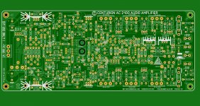
Just a quick note: some part designations are wrong, and the note lists the wrong transistor to be mounted on the heat sink.
And the second board, one to be piggybacked, is still to come any day now.
The end result should be a complete power module, with everything but the large filter caps on it. So someone may want to install say 3 in one case.
Also in the works is the basically same amp adapted to half the nominal power, 50/100 W into 8/4 Ohms, but REALLY pushed into pure class A.
Then I would have enough to upgrade my loudspeakers into fully active.
Nigel was talking of the Diffmaker type of thing, which apparently struggles with variations of timing, phase and frequency in certain situations, even though that is what it's designed to deal with.What are those tiny variations with zero audible impact? As I mentioned earlier, the key is for the test setup to be periodically making a linear model of the circuit under test (gain, delay, phase, frequency response). What's left is not linear, and so may not be dismissed as having zero audible impact.
Yes, a sophisticated enough mechanism will do the job - just requires someone to be motivated enough to make it happen ...

Godfrey, again - if we knew all there was to be known to be able to make a shall we say credible amplifier, many would be doing it.
Yet, they are not. Most sound generally artifical, implyong but not really conveying the musical message.
Now, why would that be? Poor designer education?
Musical message may be conveyed perfectly played even as wax cylinder. Very little realism is required for this, only ability to listen to the music, and let it inside the mind.
As per credible amplifier, once non-linearity and noise are controlled, differences between specimens playing same speaker reveal only differences in transfer function of how load couples with amplifier as system. Quotient of transfer function of system using amplifier A, with transfer function of system using amplifier B may be used to both express the difference between the two amplifiers, and to null the perceived differences between the two systems.
Amplifiers with no effective load, transfer no real information. Gross distortion and gross noise are obvious defects that are easily avoided.
This is a little more difficult with electro-acoustic transducers, but is readily achieved to levels of statistical significance over large population of listeners, using wide range of source signals. This is in ballpark of 0.1%-1% THD and encompasses IMD as well, and fits my personal experience.
Once noise and gross distortion are accounted for, information is neither created or destroyed by transmission system, only rearranged in completely reversible manner.
To wit; any recording is discrete in time may be convolved with MLS pattern that renders recording as noise to human perception. Convolution with reverse MLS returns recording to original state.
Likewise a discrete signal may be digitized. When this is played on analog system is sounds like noise, but original waveform is perfectly reconstructed by transfer function of D/A converter.
Capturing sound on wax cylinder was based on observation that sound causes physical vibration, and that physical vibration causes sound. Sound quality made little advancement until quantifiable, repeatable measurements were made possible.
With a THD of 0.3%, 20-20,000 Hz, 100WRMS/8 Ohms
Is that a real speaker load, simulated load, or a resistor?
Nigel was talking of the Diffmaker type of thing, which apparently struggles with variations of timing, phase and frequency in certain situations, even though that is what it's designed to deal with.
Yes, a sophisticated enough mechanism will do the job - just requires someone to be motivated enough to make it happen ...
I think we might see the sun rising soon on this . Square-waves from speakers , yes please . Standard measurements are extremely important as quality checks . Not least for staff who do not have the passion of the designer . Arcam kept a complete record of everything on the A60 , it ran to many pages ( 43 checks ? ) . As Chris Evens told me seldom did they see a variation . They felt they owed it to the customer to do that . Test anyway and record it . That amplifier was special , the others they made were unmemorable .
The other day I took my dad out to the steam trains . We saw the beautiful 8F at Toddington . The driver I guess 71 was telling me how he passed on steam yet always drove Diesel . The 8F in retirement was his first real steam experience . I said how funny , me too with valves . I did 90% valves at college and never touched them until now . Glad I did as it has taught me so much I didn't know . It also told me much about transistors , all good things .
Dvv . The Krell you so much admire . I have a hunch yours would please me better .
A friend called his amp the ID . It was the ID of the Krell that was trying to kill those of the Forbidden Planet .
The Tempest , the Id of men .
Here is another ( I will be 106 ).
Fireball XL5 25-The Forbidden Planet Part 1 - YouTube
A friend called his amp the ID . It was the ID of the Krell that was trying to kill those of the Forbidden Planet .
The Tempest , the Id of men .
Here is another ( I will be 106 ).
Fireball XL5 25-The Forbidden Planet Part 1 - YouTube
What are the main obstacles to 'The Null Test'?
You can't enter twice to the same river. You can't "null" all dynamic processes, especially deviations that matter more than others easier to null. 1% may be invisible on graph, but it is -40 dB that is audible. Real measurements are a little bit different from those you can read about and imagine.
My experience is that the distortion that matters, the "bits" that make people prefer one system over another, are dynamic in behaviour:
Exactly. And the best way to minimize them I found, to create test environment that stretches distortions in question, so they are easier to observe, and to decide what and how to tweak to minimize them.
Nigel was talking of the Diffmaker type of thing, which apparently struggles with variations of timing, phase and frequency in certain situations, even though that is what it's designed to deal with.
Yes, a sophisticated enough mechanism will do the job - just requires someone to be motivated enough to make it happen ...
Yeah, like null-test elephant and mosquito and adjust the elephant so it can fly.
Easy!
Is that a real speaker load, simulated load, or a resistor?
For the time being, just the simulator, working into an 8 Ohms +/-10% load.
As UI mentioned, my simulator has NEVER ONCE failed me, or even just lied a bit to me. And if it is off, it's always for the better, it says say 300 kHZ, and actual sample hits 350 kHz.
While it is obviously a good simulator, another reason for this I believe is the fact that I make very sure proper part tolerances are correctly noted. Capacitor - 20% tolerance, resistor - 1 or 5 % tolerance (5% for Motorola MPC series, as quoted by Motorola and as experience confirms), etc. I am amazed how people tend to overlook this obvious aspect, and often simulate with no tolerance parts, i.e. prefect parts.
Let me repeat - all that is nice and fine, but until I have an actual, working unit in front of me, I will doubt.
Dvv . The Krell you so much admire . I have a hunch yours would please me better .
A friend called his amp the ID . It was the ID of the Krell that was trying to kill those of the Forbidden Planet .
The Tempest , the Id of men .
Here is another ( I will be 106 ).
Fireball XL5 25-The Forbidden Planet Part 1 - YouTube
Nige, I won't know until I actually make it. Yes, it looks good on electronic paper, but real life can play funnies on one.
If it makes the grade, I will send you the PC boards. If I make it to the UK this September, I will bring them with me. German made Mil Spec glass fibre board, 70 micron copper layer, fully metalized through holes.
As for being better than Krell - easy there, big fellow, you don't just stroll in and beat Dan D'Agostino, our John Curl, Richard Miller of HK, and so forth. These are seasoned, proven veterans. And if you do, that's not you, that's blind punk luck. I do this for fun, they make their names and living from it, and that's one HELL of a difference.
Although, I am a several days past 60 punk old fart, slightly odd, even more slightly eccentric, and I do keep your company ...
I cannot understand all this talk about amplifiers' sound .
I take for sure that not all amplifiers neither "measure" nor "sound" exactly the same because maths can show that, but I guess the point is to take into account that by considering competently designed amplifiers, they will have its "diferences" buried under the hearing noise floor and heavily masked by loudspeaker+room and psychoacoustics behaviours.
As far as I know we are completely unable "to take our brain, speakers and room out of the equation", so I keep misunderstanding how you are trying to measure and compare our "emotions", let alone the reverberant field in the room that's only statistically characterized...
.I take for sure that not all amplifiers neither "measure" nor "sound" exactly the same because maths can show that, but I guess the point is to take into account that by considering competently designed amplifiers, they will have its "diferences" buried under the hearing noise floor and heavily masked by loudspeaker+room and psychoacoustics behaviours.
As far as I know we are completely unable "to take our brain, speakers and room out of the equation", so I keep misunderstanding how you are trying to measure and compare our "emotions"
, let alone the reverberant field in the room that's only statistically characterized...
Last edited:
I think the reason we do talk about it is we are surprised we can hear it . I feel slightly elevated that somehow I rise above the science . Shakespeare put it well .
"There are more things in Heaven and Earth, Horatio, than are dreamt of in your philosophy."
I do remember CD players were perfect which meant I wasn't as I didn't like them . Then it was decided they had degrees of perfection . Doubtless all degrees dreamt of in their philosophy ?
"There are more things in Heaven and Earth, Horatio, than are dreamt of in your philosophy."
I do remember CD players were perfect which meant I wasn't as I didn't like them . Then it was decided they had degrees of perfection . Doubtless all degrees dreamt of in their philosophy ?
- Status
- Not open for further replies.
- Home
- Member Areas
- The Lounge
- Sound Quality Vs. Measurements