It might be . I recently built a zero feedback amplifier which has 0.03 % THD at 0.63W . It was better than that down to 50 uW . It used the opposite distortion of a pentode and triode . Pre distrotion I suppose . If all triode it had considerably more distortion ( 5 % full power ) . The amplifier made the Old DIN4550 just . If I remember correctly 0.1% THD at 1.6 W . It doesn't seem much to shout about , however for a zero feedback SE design it is very good . 2 valves and 0.56V in for 8V out .
I am not comfortable that it is a low distortion design . It looks like low distortion . The sound is rather good . I notice multi-tracked voices like never before , especailly if the same voice . I have been offered some 211 valves to see if a few more watts can be had . Bass is not the greatest . I hope to try it with Quad ESL 63's soon as they do not require high damping factor . I certainly feel the all triode version was inferior . Along the way I tried Schade feedback , I have doubts about it . I would liken the effect of my design to that of Ultra Linear feedback although this is not feedback . Have I become a valve convert ? No , if anything the other way . I certainly have enjoyed doing it .
Nige, the prototypes I am working on for myself (still two, a single ended input version and a fully complementary version, I still can't make up my mind which is it going to be), both have a THD of less than 0.15% at 1 kHz, full nominal power (28.3 Vrms) into 8 Ohms, and less than 0.35% 20...20,000 Hz, both with no global NFB. By 50 kHz, this is 0.7%, but the power output is down to 21.5 Vrms.
Now, some will say fine, but that's the simulator - true, these are the simulator provided figures, but I do believe in them because that simulator has never lied to me, or let me down. But I agree, the proof of the pudding is a live model which can actually do that.
However, in my view, more important than low THD figures are stability (without which we have nothing), a good harmonic decay behavior and as symmetrical as possible slew rate (i.e. as similar as possible rise and fall times, 10-90% and 90-10%).
Just my 2 cents' worth.
Hi DVV . I suspect it has some feedback mechanisms ? Super spec .
As I understand it any transition resistance device will have a curved voltage transfer characteristic . A tiode is much like a transistor if enhanced to a pentode form . The triode has internal feedback is the simplistic way to explain it's linearity .
My amp has cathode resistors which do cause some degeneration . They are to limit current . If I was to use fixed bias I could eliminate that doubt . I am fairly certain I would still have the low measured distortion from an amp with no obvious negative feedback .
The big deal is that triode- triode is high distortion as usually seen . Pentode-triode is low distortion . I can even make mostly second harmonic doing that if accepting a higher overall distortion . Negative feedback is doing the same thing . The difference being that the negative feedback is slightly time delayed and not the curve that the device has . I have to say on balance global negative feedback is our best friend as it gives low output impedance as a bonus . I have found valves and global feedback seldom doing nice things . Having built this amp I feel I completed my training I started 38 years ago . That was plotting a pentode curve in my exams . Never touched a valve since except to do a few repairs . I now feel qualified to talk when they are discussed . Not super qualified I admit .
As far as I can see no amplifier can have low distortion and zero feedback . Most people mean zero global feedback , that's different . My amp might be as close as one can get . With a 211 I might get 5 watts 0.1% THD by this route and 20 W before too nasty . Class D may well be different .
Hi DVV . I suspect it has some feedback mechanisms ? Super spec .
Of course it does, for a kickoff, its input stage(s) use degeneration to cut the gain down to 6.8:1 or so, 220 Ohms emitter resistors, 1.5k collector. I don't see how one can make an amplifier with literally zero feedback, no local NFB, no global NFB.
As far as I can see no amplifier can have low distortion and zero feedback . Most people mean zero global feedback , that's different . My amp might be as close as one can get . With a 211 I might get 5 watts 0.1% THD by this route and 20 W before too nasty . Class D may well be different .
That's what I said a few posts above. To me, the idea is a perversion of the generally sane idea that it's good to reduce global NFB and increase local, however, to really work well, even that has to be carefully balanced and judged. My own proposed figure of 26 dB global is a tentative value only, a very general guideline, not a rule carved in stone. Quite simply, my experience is such that this figure is about right, but how you reduce distortion to the point where that is enough global NFB is up to you.
Then again, as you know, I have my own topologies, the ones I like and am comfortable with - change them for others and it's back to the drawing board. Give me weird, Sony-like topology, and I need at least a month to even understand it to the point where I can intervene. For HK, I need five minutes to determine which version is it from about three general topologies they used or use, and I can do things with it, for better or for worse.
As for the THD figures you quoted at low power levels, I must say mine are usually completely beyond reliable measurement, i.e. below 0.001%. That's because I like to run my output stages relatively "hot", with a bias current of about 120...140 mA per transistor. Remember I use never less than 3 pairs, and often 4 pairs, so my sub-1W power is well within pure class A operation and is supported by at least some global NFB, yielding vanishing distortion figures.
BUT, also remember this - I make such things for myself only, they are NOT commercial products, so literallly ALL of the production run constraints simply do not exist. Most folks here, who work for the industry at large, are far from being that lucky, and I would say that I believe they are often enough forced by price constraints to use less to much less of what they'd like to use.
I use 7 lb heat sinks by default, and if there's need, I'll just throw in another heatsink per side for good measure. I'll turn a stereo amp into a monoblock in a jiffy if I feel like it. I'll throw in as many capacitors as I think it should have, not thinking about costs for even a second. To me, it's all fun and games, but to them, it's professional work, it's business, an entirely different ball game.
And make no mistake, I respect their achievements more than I respect my own, precisely because I know most of the constraints they had to deal with to get there. It's much easier to be good with no contraints.
Last edited:
I have seen this in the past and some kindly Members have given formulae to determine this........................... a classic bipolar differential pair should have an overall gain of no more than 11:1, and no less than 5:1, and the in-between values would show up the bipoars at their very best, .............
But here I have sinned. I have not saved, nor remembered the details.
Could you give your method of determining the component values with an example calculation?
DVV . Have you ever tried using one of you amps with a gain > 100 ? It would be to use a passive preamp on tape decks like Nakamichi . I did it once and loved the outcome . A friend found it too noisy with 100 dB sensitivity speakers ( what was that about ! ) . Distortion was still very very low as would be yours . You have a damping factor of 6 so do not need even 26 dB of feedback ( 10 dB ? ) . I must make that amp again , I gave my last one to a lad who worked for me . I wanted to make a volume control for it that eventually reduced the feedback as volume increased . The control would be part conventional and part feedback relaxation . At no time would the amplifier produce unacceptable levels of distortion ( < 0.05% THD with nice harmonics ) . Damping factor would stay at > 10 . It would have an override so as to use an active preamp . I would liken the experience to Guitar amps . Yes there are a few minor issues when not listening to music . When the music plays that is forgotten .
I can imagine most amps have an optimum feedback arrangement . Like the very good suggestion yesterday of an op amp with gain 3 sounding worse I am sure most amps have a bad and good point that is closely spaced .
I can imagine most amps have an optimum feedback arrangement . Like the very good suggestion yesterday of an op amp with gain 3 sounding worse I am sure most amps have a bad and good point that is closely spaced .
I have seen this in the past and some kindly Members have given formulae to determine this.
But here I have sinned. I have not saved, nor remembered the details.
Could you give your method of determining the component values with an example calculation?
Och man, I already confessed to a crime the same as yours, that of not saving good stuff, and I am now haggis meat myself.

Actually, we have a form of haggis down here in Serbia, as well. Similar, but not the same. But similar enough to help me feel like a distant cousin when visiting Scotland in 2009. LOVED IT!
Translinear circuit - Wikipedia, the free encyclopediaAs far as I can see no amplifier can have low distortion and zero feedback .
DVV . Have you ever tried using one of you amps with a gain > 100 ? It would be to use a passive preamp on tape decks like Nakamichi . I did it once and loved the outcome . A friend found it too noisy with 100 dB sensitivity speakers ( what was that about ! ) . Distortion was still very very low as would be yours . You have a damping factor of 6 so do not need even 26 dB of feedback ( 10 dB ? ) . I must make that amp again , I gave my last one to a lad who worked for me . I wanted to make a volume control for it that eventually reduced the feedback as volume increased . The control would be part conventional and part feedback relaxation . At no time would the amplifier produce unacceptable levels of distortion ( < 0.05% THD with nice harmonics ) . Damping factor would stay at > 10 . It would have an override so as to use an active preamp . I would liken the experience to Guitar amps . Yes there are a few minor issues when not listening to music . When the music plays that is forgotten .
I can imagine most amps have an optimum feedback arrangement . Like the very good suggestion yesterday of an op amp with gain 3 sounding worse I am sure most amps have a bad and good point that is closely spaced .
I have seen the concept, Nige, even used it on a few occasions. However, it has not stuck to me. I suppose mostly because I am used to building preamps with 50W power devices at their output, delivering a stunning vibrant bass line if required that no passive device I ever heard (a total of 6) ever really captured my imagination.
A good friend makes his living by making passive preamps and selling them all around Europe for something like € 2,500 (app. $ 3,200), and he's been trying to get me hooked for years, but sorry compadre, no go. To my ears, passive devices somehow take some of the brute energy out of the signal, and I just plain hate that.
It could also be a placebo effect for all I know, but whatever the reason, they don't do it for me.
@Nigel
I forgot ... While it's of course possible to give an amp a closed loop gain of >100, I NEVER do that.
If you look over the range of what is considered to be High End today (Krell, Levinson, Accuphase, etc), you will be able to see that most of them operate with a closed loop gain of 25...30:1, rarely more. Obviously, the greater your input signal, the less overall gain you need to get it up to what you need. Therefore, their input sensitivities for nominal power output range from approximatels 1V to 2.5V.
I find that to be quite resonable for two reasons. First, literally ANY active premp worthy of that name should be able to deliver that kind of voltage no problemo, and at least twice more over and above that, including all op amp preamps; if memory serves, the lowest maximum output voltage I have ever seen was 6.5 V, and most will do better than that. Second, the nominal power amp output voltage is, in many cases, way over what is actually required - with a gain factor of 30 and an input sensitivity of 2.5 V we are talking powers of 700+ Watts per channel into 8 Ohms, or in our buddy Wayne's case, 5,600 Watts into 1 Ohm. While entirely possible, that kind of power does not come cheaply, you do need a pretty hefty power supply and a fine line of output devices to get there.
I suspect John may have a comment or two on this matter, this is right up his alley.
Brad, I did take a look, but I won't pretend I understood everything perfectly. My reasoning is: if one has one transistor driving another and another, and we assume each transistor has a gain of only 50:1, by the end of that route the signal would have been multiplied (50x50x50) 125,000 times.
If not, then we are using some form of degeneration, or local feedback, along the way, no matter how exotic it may be.
If you are better acquainted with this principle, please correct me if I'm wrong.
I should have explained a bit, as the article is both more detailed and less to-the-point of the discussion.
Basically, the notion that is relevant: for a current amplifier in particular, the translinear circuits "predistort" the signal and compensate for the bipolar Vbe nonlinearity, without global or even local feedback.
The simple example is a two-transistor current mirror. Then use a larger emitter area for the output device, or multiple paralleled devices, and to a first approximation, the current gain scales with the areas. I'll get round to posting some examples.
Barrie Gilbert, who uses the approaches with great skill, reported results for multipliers and other variable gain stages with distortions in the vicinity of -80dB. This was in the 1960's, and as they say, he's kept it up
Thanks for this link . I don't think I would have interpreted it this way had I stumbled upon it . I especially welcome the reference to a current mirror . Well beyond fascinating I would say . I told my girlfriend she is fascinating . I hope she never reads this thread . I am fairly confident she never will .
my brain just frazzled.
Andrew it's the pretty pictures I like . I was reading Ultra Linear feedback the other day and there were pretty pictures in that . Suddenly the bleeding obvious jumped out of the pages . It is well worth a read . My brother refused to class UL as feedback . If anyone is so inclined I have a link .
ultra-linear
ultra-linear
It is just using the fact that for a BJT over a wide range of currents, the output current is proportional to the exponential of Vbe. Turning it on its head, Vbe is proportional to the logarithm of the current. With logs and exps you can multiply and divide. The clever bit is losing the base current, which is an error term and unpredictable.
Going back to feedback:
Other things being equal, you can maximise linearity by maximising global feedback and minimising local feedback. This is because local feedback only linearises one stage (and possibly its immediate neighbours via impedance effects), while global feedback linearises the whole thing. There is even an argument for adding local positive feedback around the most linear stages to boost loop gain and help linearise the less linear stages.
Other things are not equal. Phase shifts limit the amount of global feedback you can add, as more than three rolloffs (typically, three stages) create scope for instability. Overload (voltage or current) in intermediate stages limit the size of error signal which can be handled. Common-mode distortion at the feedback summing point may limit the ratio between input and error signal. Hence there may be a sensible limit to feedback at the HF end in many circuits. Much more feedback can and is used at LF.
I always say work towards a circuit that works well with global feedabck . Then all options are available . It also indicates a nice machine has be devised . I am not sure if MOS FET's allow more feedback ? It seems that way . I always found what I lost in MOS FET linearity I regained in being able to apply global feedback . I suspect overall that MOS FET's do provide the best solution if my assumption is correct . I have not bought enough of the very best bipolar transistors to say for certain .
I tried with great success the two pole VAS compensation described in Douglas Self's book . It looks like a recipe for disaster and has an unattractive hump in it's curve . It works very nicely , it offers scope for distortion reduction . It costs less than $1 per amp and < 1 hours work . The resistor can be removed to make comparisons . It should work for shop bought amps equally well . If lets say the VAS cap is 33 pF then approximately it is replaced with 39 pF and 330 pF with a 2K2 resistor to the rail . If the 2K2 is cut then it becomes 34.9 pF . There was some confusion about to the rail or ground . I think both are possible as is to the output . Please research before trying .
I tried with great success the two pole VAS compensation described in Douglas Self's book . It looks like a recipe for disaster and has an unattractive hump in it's curve . It works very nicely , it offers scope for distortion reduction . It costs less than $1 per amp and < 1 hours work . The resistor can be removed to make comparisons . It should work for shop bought amps equally well . If lets say the VAS cap is 33 pF then approximately it is replaced with 39 pF and 330 pF with a 2K2 resistor to the rail . If the 2K2 is cut then it becomes 34.9 pF . There was some confusion about to the rail or ground . I think both are possible as is to the output . Please research before trying .
It is just using the fact that for a BJT over a wide range of currents, the output current is proportional to the exponential of Vbe. Turning it on its head, Vbe is proportional to the logarithm of the current. With logs and exps you can multiply and divide. The clever bit is losing the base current, which is an error term and unpredictable.
Going back to feedback:
Other things being equal, you can maximise linearity by maximising global feedback and minimising local feedback. This is because local feedback only linearises one stage (and possibly its immediate neighbours via impedance effects), while global feedback linearises the whole thing. There is even an argument for adding local positive feedback around the most linear stages to boost loop gain and help linearise the less linear stages.
Other things are not equal. Phase shifts limit the amount of global feedback you can add, as more than three rolloffs (typically, three stages) create scope for instability. Overload (voltage or current) in intermediate stages limit the size of error signal which can be handled. Common-mode distortion at the feedback summing point may limit the ratio between input and error signal. Hence there may be a sensible limit to feedback at the HF end in many circuits. Much more feedback can and is used at LF.
Beggin' yer pardon, commodore, this seems to hark back to my hypothesis that the best OVERALL solution is to use a well judged balance between local and global NFB.
Too much of either will not end well for the sound.
Because of the variety of possible topologies, and the way one handles them, there is no one-fit-all formula. I shall be presumptious here and say that this where the art of HEARING rather than merely listening comes in, this is the part where the engineer meets the artist - in making the best possible balance between the two for any given circuit topology.
Experience helps a lot here. For example, I know that when I make a cascode with a gain factor of 6.8:1, if using a lower pair FET (2SK170) with a total bias of 3.65 mA, or if using a pair of low noise BC 550B bipolars with a total bias of 2.2-2.4 mA, my input stage is done. Having made it at least 59 times over the last 10 years, I have had ample opportunity to make sure it really is if not THE best, than at least the next absolute best.
I know what my predriver-driver-output stage will look like, again, I have tried it several times in the past and it does work like a charm indeed. One 5W BF trannie driving MJE 50W drivers, driving 4 pairs of MJL 200W devices (or 3 pairs of MJ 21195/21196 250W devices), you can hardly fail (of course you can, but you really have to be dummy to do so badly).
Which leaves you with the VAS stage. If you only assume that this too will be a cascode, then your work is greatly simplified. Basically, you are left with a few dilemmas, for example should you use a buffer stage between the input and the VAS, should you use dual supply lines, shoud the VAS line be regulated or not, and if yes, which regulator, etc.
Personally, I'm not so much turned on by the fact that my distortion levels decrease somewhat if I throw in a buffer stage between the input and VAS, I could even say that the difference was not worth the time and trouble, but by the fact that it completes the 100% cycle of input being totally cut off from the output - which is good news if you happen to be driving an evil load. Much the same for the predriver in the current gain stage.
Obviously, this complicates the entire thing. Transistors start turning up everywhere for this or that. The crude part of the DIY gang, the transistors counters (people who believe that the less transistors there are, the better the sound, but deny that the best sound is produced by zero transistors
), are appaled at the semiconductor count. They fail to realize that many, or even most, of the power amps considered to be the best in the world, are extremely complex. For example, the Krell FPB series has no less than 118 transistors in the VAS stage only (common MPS series all of them), Levinson is not quite so complex but is not far behind, etc, and the man they swear on, Nelson Pass, may have created the Zen and its family, but in his Threshold commecial series, he uses like 60 output devices alone.And it's a LOVELY point of argument between Nige and me.
Last edited:
I think what DF 96 is saying is for the ideal amp global feedback always wins . To me it does as it has the low impedance output advantage ( the free lunch ) . It is also the only way as far as I know to tackle crossover distortion ( if I am wrong so be it ) ? He also says why ideal is limited by stability etc .
I do believe that op amps tell us an ideal amplifier is possible . After all a power amplifier is an op amp . As much as I know I will regret saying this I do believe if cables can affect sound an op amp at unity gain might be less degrading . I don't want to open the cable debate except to say I have come to beleive it is connectors if anything .
Sometimes technically op amps perform less well at a gain of 3 compared with unity . My ears thought so also . With a power amp I doubt we would easily be able to do such a test . Happy to be wrong . Very likely a unity gain power amp with good stability would sound superb .
I have never tried one of my power amps at unity gain . I must try . I have tried at very low gain and liked what I got ( 7 ? ) .
You may have gathered I often say things which if the soldiering iron was in use I wouldn't do . I say it to know what others think and why . I never dreamed to get the link on current mirrors . Worth it . I feel a bit embarrassed it didn't occur to me that is how they work .
Honda proved many years ago how to make ideal engines . We none do and they know why . Close to ideal is fine . Practical is even better . Inexpensive is better still . I think I am right in saying the Italians had V8 500 cc bikes in 1953 ? Norton challenged them with a single . I think the V8's were banned . In audio we can have what we like within reason . Funny thing is Norton didn't always loose to the exotic bikes . It was by refinement very fit for it's job . It probably took your teeth out doing it !
adequate bias is required to reduce crossover distortion - no amount of feedback can make the output not have a deadband if under biased - high loop gain feedback can only try to drive the output Q harder, faster through the deadband
local feedback loops can be "nested" around the output stage - which is often the highest distorting stage of an amp: Hawksford/Cordell "Error Correction", TMC, Cherry's Nested Differentiating Feedback Loops
the local gain can help smooth out output stage errors like gm doubling or beta droop - as long as they aren't too extreme and the gain never goes to zero
even the near universal use of unity gain emitter/source follower output Q stages is local output stage feedback
Cherry does point out some advantages can be had with common emitter/source high gain output stages - but in practice they aren't as popular except in the pro PA floating supply amps by QSC et al
basically Cherry's claim is that V gain in the output stage is a good thing for distortion reduction in ealier stages, and no worse or actually the same as using the output devices devices in follower mode in terms of output impedance and stability
the low drive voltage at the bases/gates of grounded emitter/source output stages requires only low voltage input/driver devices which enable faster transitors or even op amp drive
Last edited:
I like nested feedbacks. For example, in Pyramid amps I have quite deep global feedback and quite low distortions (-80 dB of 2'nd order only on 40W), but corner frequency for compensation is about 15 kHz, quite high, despite the output transformer (10K P-P 100W from 20 Hz) is ringing on the frequency about 30 kHz.
Local feedbacks also greatly help to control behavior on transients (if made properly!).
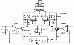
Here is one more interesting amp with local only feedbacks (attached, from vintage magazine). Output stage has deep local feedback by voltage and input resistance of few kiloohms only. Driver has deep feedback by current and high output resistance. The overall result is quite remarkable.
Local feedbacks also greatly help to control behavior on transients (if made properly!).
Here is one more interesting amp with local only feedbacks (attached, from vintage magazine). Output stage has deep local feedback by voltage and input resistance of few kiloohms only. Driver has deep feedback by current and high output resistance. The overall result is quite remarkable.
Attachments
- Status
- Not open for further replies.
- Home
- Member Areas
- The Lounge
- Sound Quality Vs. Measurements