Good approach, Wavebourn.
I would be surprised if it was not patented yet,
Which is exactly what Dan d'Agostino did and used them for, a very complex arrangment.
For audio, I usually swear by BF 720/721 - a transistor with uncommonly low distortion and actual, effective Ft. But I find that two parallelled MPSA 42/92 devices actually beat him all around, albeit by just a little. Also, their price is so ridiulously low that you can easily afford a large population from which to select them easily. In a handy, TO-92 package.
Maybe you need a good phono pre -amp ...
")
Mark Levinson JC2 preamp with phono (collectable) | eBay
Supposedly good .... !!!
First conclusion: two 1N4148's do a far better job of being a voltage reference to the single transistor ccs than a red or green, all else the same ( emitter resistor adjusted for the same current.) What effects the high frequency response is the transistor. I wish I had models of more parts, like the 2SC1085. BC5550 does pretty well over the 2N5551. Te other curious thing is that the current with LED's does nasty glitching when the diff pair turns off.
Putting in a big cap, (220u big enough?) did not have effects in the simulator. Reality may well be a different story. I see that done on the "mx50" boards.
Now to play with zeners and maybe fancy new fast soft recovery diodes if I can find a model.
Putting in a big cap, (220u big enough?) did not have effects in the simulator. Reality may well be a different story. I see that done on the "mx50" boards.
Now to play with zeners and maybe fancy new fast soft recovery diodes if I can find a model.
Wadax looks like an exercise in over-the-topness.
My sentiments too - the reviewer seemed to mention the 6.4Gbit/s bandwidth between their FPGA and the external memory somewhat in hushed tones as if spraying bits around the PCB incredibly quickly indicated superior engineering skills
Of course. Dynamic resistance of the LED is 4-5 ohms... What cap you need for that?Putting in a big cap, (220u big enough?) did not have effects in the simulator.
You know what part of specs did make me laugh? This one:My sentiments too - the reviewer seemed to mention the 6.4Gbit/s bandwidth between their FPGA and the external memory somewhat in hushed tones as if spraying bits around the PCB incredibly quickly indicated superior engineering skills
"USB lock range(KHz): No driver is needed. 48 KHz, 16-24 bits"
Oh... really??? Awesome, only if TI would get a hold of THAT marvel...
Last edited:
Hard to beat the original configuration. Tried cascode and feedback, tried zenier, tried cap. Small differences, give and take. Three conclusions: Pair of diodes beats an LED, transistor matters a lot more, and fancy configuration does not buy much.
I bet everyone knew that.
I bet everyone knew that.
First conclusion: two 1N4148's do a far better job of being a voltage reference to the single transistor ccs than a red or green, all else the same ( emitter resistor adjusted for the same current.) What effects the high frequency response is the transistor. I wish I had models of more parts, like the 2SC1085. BC5550 does pretty well over the 2N5551. Te other curious thing is that the current with LED's does nasty glitching when the diff pair turns off.
Putting in a big cap, (220u big enough?) did not have effects in the simulator. Reality may well be a different story. I see that done on the "mx50" boards.
Now to play with zeners and maybe fancy new fast soft recovery diodes if I can find a model.
See my signature.
Small differences, give and take. Three conclusions: Pair of diodes beats an LED, transistor matters a lot more, and fancy configuration does not buy much.
I bet everyone knew that.
I didn't. Experimentally, a red LED gives lower impedance and noise than a pair of diodes.
Hi,
Yes, cutting records (especially all manual) is a serious art and one that is dying out. I wonder how many cutting engineers are left that can simultaneously read the score, gainride (to avoid overload or automatic compressors) and control the groove spacing at the same time AND get a perfect result almost every time!
Most folks simply do not know what went into making a record, from the master tape on a Revox C37, to cutting a lacquer master, via the various stages of electroplating to punching the centre hole and eventually pressing (and how many chances to screw it up royally).
Next to that making a CD Glass Master is trivial, though most of the time the CD pressing plants get that wrong too...
Ciao T
Lots of great work, I don't think these folks get enough credit.
Yes, cutting records (especially all manual) is a serious art and one that is dying out. I wonder how many cutting engineers are left that can simultaneously read the score, gainride (to avoid overload or automatic compressors) and control the groove spacing at the same time AND get a perfect result almost every time!
Most folks simply do not know what went into making a record, from the master tape on a Revox C37, to cutting a lacquer master, via the various stages of electroplating to punching the centre hole and eventually pressing (and how many chances to screw it up royally).
Next to that making a CD Glass Master is trivial, though most of the time the CD pressing plants get that wrong too...
Ciao T
Hi,
Funny thing, a good cutting engineer will do just like that, listen to the tape for the whole side, take notes of the time and what stands out, maybe listen again and then just sit down, gain control in one hand, groove spacing in the other, time display, score and notes taped up somewhere and cut.
For D2D cuts replace "listen to the tape" with "attend rehearsals".
Ciao T
The best way is to use digital delay once, recording resulting sidechain, then apply this sidechain to direct actual recording without any delays. Just 2-step procedure: adjust well then shoot once.
Funny thing, a good cutting engineer will do just like that, listen to the tape for the whole side, take notes of the time and what stands out, maybe listen again and then just sit down, gain control in one hand, groove spacing in the other, time display, score and notes taped up somewhere and cut.
For D2D cuts replace "listen to the tape" with "attend rehearsals".
Ciao T
I posted some tail current ccs options in http://www.diyaudio.com/forums/solid-state/86626-searching-best-ccs.html#post1006904
a resistive bootstrap ccs is used by Hugh Dean, "Aska"
combining the bootstap tail ccs with a 2 term fet/crd ccs gives very low simmed distortion in the tail current
a resistive bootstrap ccs is used by Hugh Dean, "Aska"
combining the bootstap tail ccs with a 2 term fet/crd ccs gives very low simmed distortion in the tail current
I posted some tail current ccs options in http://www.diyaudio.com/forums/solid-state/86626-searching-best-ccs.html#post1006904
a resistive bootstrap ccs is used by Hugh Dean, "Aska"
combining the bootstap tail ccs with a 2 term fet/crd ccs gives very low simmed distortion in the tail current
JCX, just one question: how much, in your opinion, does the actual quality of the power supply influence CCS results?
I did read a few pages of the link you posted, and it seems the discussion was started by a man from Germany who uses simple RC filtered power lines. But what if the power lines were all of that, and then additionally filtered by a full voltage regulation circuit?
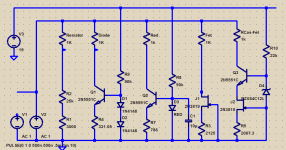
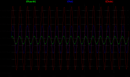
More reading, more ideas. Cool. Yes, even I have figured out the model is several viewpoints among many and truth comes on the bench and in the listening. One of the things I found out was the odd glitch double bounce was an artifact of the feedback, not the ccs itself. Of course, how it handles it is the question. I am going to simplify the model today. What I think I should be looking for is how it handles a step in load. My reasoning tells me that implies the impedance as well as the transient behavior. So I have been looking at a plot of the tail current with a square wave load. Consistency over absolute impedance. Reasonable? Then in a complete amplifier model to look at the distortion.
Ok, so the LED is a lot better, and a cascode BJT/FTE much better still. Now, to figure out how to put offsets on the Spice traces to make comparisons more obvious. Plot is current through the load.
Transistor selection was by what was in Spice. Current adjust to be close, not any magic value.
Transistor selection was by what was in Spice. Current adjust to be close, not any magic value.
Attachments
Hi,
A non-ideal tail current source will cause common mode related problems, if the impedance is relatively low and frequency dependent we are in trouble.
JCX's "resistive bootstrap" comments came at a good time (as did Dejan reminding me of paralleling small signal parts), as it completed at least for the concept stage something I have been fuzing and munzing with, so at least now I have something to feed to LT-Spice (if I can find models for 2SK214/2SJ77) or just do re-build for real...
FWIW, here my take on what to implement in a nice case, with a pair of 0.3K/W heatsinks and a 1200VA mains transformer...
Anyway, we want the CCS impedance both high, linear and frequency independent.
Ciao T
PS, the attachment has not been build or tested (yet), but is intended to be implemented to some existing hardware, using existing PCB's and as many existing parts as possible, while getting something more to my liking.
There are details not shown (such as the ferrite beads or resistors as base/gate stoppers, protection circuitry, other housekeeping and so on which is in place in the actual unit and will be retained) and the final compensation is not fully worked out yet, it will probably need two small miller compensation caps as well.
Consistency over absolute impedance. Reasonable? Then in a complete amplifier model to look at the distortion.
A non-ideal tail current source will cause common mode related problems, if the impedance is relatively low and frequency dependent we are in trouble.
JCX's "resistive bootstrap" comments came at a good time (as did Dejan reminding me of paralleling small signal parts), as it completed at least for the concept stage something I have been fuzing and munzing with, so at least now I have something to feed to LT-Spice (if I can find models for 2SK214/2SJ77) or just do re-build for real...
FWIW, here my take on what to implement in a nice case, with a pair of 0.3K/W heatsinks and a 1200VA mains transformer...
Anyway, we want the CCS impedance both high, linear and frequency independent.
Ciao T
PS, the attachment has not been build or tested (yet), but is intended to be implemented to some existing hardware, using existing PCB's and as many existing parts as possible, while getting something more to my liking.
There are details not shown (such as the ferrite beads or resistors as base/gate stoppers, protection circuitry, other housekeeping and so on which is in place in the actual unit and will be retained) and the final compensation is not fully worked out yet, it will probably need two small miller compensation caps as well.
Attachments
Hi,
Try the attached...
The LM329 you can probably get a good aproximation with a voltage source, a resistor and an inductor... Rest can use real devices, BC550C simply means small signal NPN high beta...
Ciao T
Ok, so the LED is a lot better, and a cascode BJT/FTE much better still.
Try the attached...
The LM329 you can probably get a good aproximation with a voltage source, a resistor and an inductor... Rest can use real devices, BC550C simply means small signal NPN high beta...
Ciao T
Attachments
Jung's been doing a lot of study of various current sources recently --- I haven't checked to see if he's "published" them on his website.
One of the things that came out was the brief note in a paper by Jaeger about adding a JFET to the output of a simple bipolar I source, and returning the gate to the emitter. This of course resembles a "Hawksford" cascode (with actual priority for biploars probably accorded to Aldridge in 1962 as I've babbled about before), and besides the convenience of biasing, returns the Cdg displacement current to the emitter, and vastly reduces the effective output capacitance (and hence any distortion associated with its variation with voltage). As well thermal shifts in the bipolar with signal swing are reduced. The drawbacks include voltage burden.
One of the things that came out was the brief note in a paper by Jaeger about adding a JFET to the output of a simple bipolar I source, and returning the gate to the emitter. This of course resembles a "Hawksford" cascode (with actual priority for biploars probably accorded to Aldridge in 1962 as I've babbled about before), and besides the convenience of biasing, returns the Cdg displacement current to the emitter, and vastly reduces the effective output capacitance (and hence any distortion associated with its variation with voltage). As well thermal shifts in the bipolar with signal swing are reduced. The drawbacks include voltage burden.
Hi,
While "all analogue" LP's do exist, you would be surprised how many actually went through a 14 Bit/48Khz digital delay (IIRC - it may have been 16 Bit) during cutting to automatic control of groove spacing...
Ciao T
Still sound better nail dragging .......
Hi,
A non-ideal tail current source will cause common mode related problems, if the impedance is relatively low and frequency dependent we are in trouble.
JCX's "resistive bootstrap" comments came at a good time (as did Dejan reminding me of paralleling small signal parts), as it completed at least for the concept stage something I have been fuzing and munzing with, so at least now I have something to feed to LT-Spice (if I can find models for 2SK214/2SJ77) or just do re-build for real...
FWIW, here my take on what to implement in a nice case, with a pair of 0.3K/W heatsinks and a 1200VA mains transformer...
Anyway, we want the CCS impedance both high, linear and frequency independent.
Ciao T
PS, the attachment has not been build or tested (yet), but is intended to be implemented to some existing hardware, using existing PCB's and as many existing parts as possible, while getting something more to my liking.
There are details not shown (such as the ferrite beads or resistors as base/gate stoppers, protection circuitry, other housekeeping and so on which is in place in the actual unit and will be retained) and the final compensation is not fully worked out yet, it will probably need two small miller compensation caps as well.
Ok , regulated flat amp stage , separate supplies , why CLC ....?
- Status
- Not open for further replies.
- Home
- Member Areas
- The Lounge
- Sound Quality Vs. Measurements