The Golden Ratio is [1 + (5^[0.5])]/2, about 1.618 (but an irrational number). It is better and better approximated by the [edit] quotients of the successive terms of the Fibonacci series, where each successive term is the sum of the two preceding ones. By the way, it doesn't matter where you start after a while, although 1 is the typical starting number and another 1 the next (hence 1, 1, 2, 3, 5, 8, 13, 21...). The series of successive quotients has an unusual distinction in being very slow to converge.
And let's send our donations to Noel, as Monster Cable has just parted ways with Beats by Dr. Dre, and he will have to scrimp and save to get his next Lambo. A marketing guy there quipped that at Monster the headphones are now known as Dead Beats.
And let's send our donations to Noel, as Monster Cable has just parted ways with Beats by Dr. Dre, and he will have to scrimp and save to get his next Lambo. A marketing guy there quipped that at Monster the headphones are now known as Dead Beats.
Last edited:
But still, I am waiting for someone to suggest how this has anything to do with amplifier circuit design.
(Actually the golden ratio is : 1.618)
That's odd, because I read about you guys discussing odd and even order harmonics, every day.
Heck even the "LOG" volume pot is golden ratio, to account for the exponential air pressure resistance at different SPLs.
The power levels needed are also exponential. Weather or not these correspond with some generally accepted rule of thumb is incidental.
lolThe Golden Ratio is [1 + (5^[0.5])]/2, about 1.618 (but an irrational number). It is better and better approximated by the [edit] quotients of the successive terms of the Fibonacci series, where each successive term is the sum of the two preceding ones. By the way, it doesn't matter where you start after a while, although 1 is the typical starting number and another 1 the next (hence 1, 1, 2, 3, 5, 8, 13, 21...). The series of successive quotients has an unusual distinction in being very slow to converge.
And let's send our donations to Noel, as Monster Cable has just parted ways with Beats by Dr. Dre, and he will have to scrimp and save to get his next Lambo. A marketing guy there quipped that at Monster the headphones are now known as Dead Beats.
Correct, pick two numbers in the sequence, say 5,8.
5 x 1.61 = 8.05 8.05 x 1.6 = 13.02 13.02 x 1.61 = 21.06 and so on.
I am, at this very moment, listening to an optimum stranded cable designed by George Cardas, first used by Enid Lumley, and it STILL sounds just fine to me. Beats zip cord, or cheap RS or Monster Cable. Go figure.
Pretty similar thing with me, as well. I am still using van den Hul's Hybrid 352 speaker cable (2x256 strands, silver plated copper with carbon fibre, hence Hybrid), which many people claim does nothing for them. Yet, it sounds just right for me.
Since due to room architecture I need faily long runs (2x6 meters, app. 2x20 ft), I suppose it's much more a matter of current capability of just about all the amps I have at hand and press into service.
At this time, cables are off my radar completely. I'm happy with those I already have.
I think you are mixing Noel with George Cardas.
However, you also really don't know much about the cable business, as well. Nobody thinks that Noel is serious, anymore, about cables. But at MARKETING, he is a genius!
I think tvr was just using Noel as a convenient and well-known historical example of a cable guy. Cardas has done a pretty decent marketing job on the Golden Section.
Yes, in the annals of marketing the man Lee stands (or in his case sits) alone. My understanding is that, as well, Monster Cable gets a signficant portion of their revenues from payments from people who were foolish enough not to realize that the company has copyrights on the use of Monster in most any way, shape, or form. I used to chuckle when I found that after purchasing the rights to call an SF ballpark Monster Park, most people thought it was after the job search site monster.com. But the latter is probably filling the Monster Cable coffers, along with the payments from hamburger stands and heaven knows what else.
I am, at this very moment, listening to an optimum stranded cable designed by George Cardas, first used by Enid Lumley, and it STILL sounds just fine to me. Beats zip cord, or cheap RS or Monster Cable. Go figure.
How did it measure .....

Monster must still be serious, they showed me their 12K speakers cable set a few months back .
Poor Elliot .....

so Shamam, who the heck was Andrew Jones? I assume a mathematician who was jealous that engineers actually get paid.
There is actually an oxymoron in your sentence.
A good mathematician is good physicist and a good engineer. Sadly it doesn't go the other way around. If you can't see it you're probably an engineer.
Andrew Jones is a physicist who currently works as an engineer.
You can find an interesting interview of Mr. Jones here (part 2 is here).
Concerning your other topic: Golden Ratio
Last edited:
Whenever one start to deal with scientific matters numbers such as pi , e , 1 , -1 or sqrt(-1) deserve more the "magic" quality attribute but i suppose that they are not as easily marketable than a number that is said to be gold made , litteraly when it comes to Audiophili$m...
Whenever one start to deal with scientific matters numbers such as pi , e , 1 , -1 or sqrt(-1) deserve more the "magic" quality attribute but i suppose that they are not as easily marketable than a number that is said to be gold made , litteraly when it comes to Audiophili$m...
But the most magic number is zero, certainly for audio. Zero distortion, zero dB variation in FR, zero difference between original and reproduction. We are asymptotically approaching all these zero's, but the logarithmic nature of the auditory system leaves us with endless opportunity to invent further improvements.
vac
tag line at the end of a Jim Williams app note:
“A part-per-million is a part-per-million. It’s magic. It’s the brass ring. It’s the holy grail of every
measurement artist. It will mesmerize you, it will goad you, it will drive you crazy and, if you’re
lucky, it will reward you. A part-per-million is a part-per-million.”
Jerrold R. Zacharias
M.I.T. physicist, mentoring a young,
very naïve investigator.
___ 1971
But the most magic number is zero, certainly for audio. Zero distortion, zero dB variation in FR, zero difference between original and reproduction. We are asymptotically approaching all these zero's, but the logarithmic nature of the auditory system leaves us with endless opportunity to invent further improvements.
Do you mean we are approaching zero sound quality and zero MTBF of cellphones and handheld music players?
Also, zero independence on music suppliers... I bought a car a month ago. With 3 months of "free" service of XM radio. Month after (today) I lost all my presets on my radio in my car and got advertisements from XM only, so had to work again restoring my presets. That means zero respect of consumers.
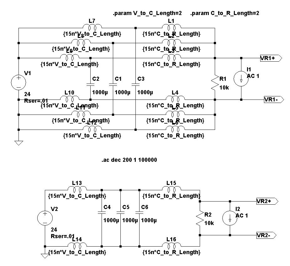
One caveat about paralleling caps. Frequently the inductance of one of them will ring with the capacitance of a smaller one, making the net impedance at the point quite a bit more complex than at first glance. One may do still better with some damping resistances placed strategically, in series with some of them.
Brad
Brad,
Concur.
Actually, that was covered pretty thoroughly in the first part of the thread called paralleling film caps with electrolytic caps, at:
http://www.diyaudio.com/forums/power-supplies/106648-paralleling-film-caps-electrolytic-caps-23.html
That's a good thread.
We also came up with methods for using frequency- and temperature-dependent LTspice models for electrolytic capacitors, able to run well in transient simulations, thanks to Cornell Dubilier's java applet that generates them automatically.
In the same thread, posts 221, 224, 252, and 257 are the main ones where I started to figure out how to calculate decoupling cap values for high power devices, based on required current peak value and rise time and allowable rail voltage disturbance, while also accounting for the effects of component and interconnect parasitics (calculating number of smaller parallel caps needed). We also went into calculating the pwr/gnd target impedance that would need to be seen by the active device, at the frequency corresponding to the worst-case risetime.
Post 292 veered off into practical snubber and termination design. Very useful.
And then in posts 310-330 we got into using multiple parallel copies of the power and ground rails and smoothing caps, to reduce the supply impedance seen by an active device. The LTspice models for that are downloadable from post 330.
It turned out that with three smoothing caps with a couple of inches of rails on each side, using three parallel copies of each rail was 50% better at low frequencies and much better at higher frequencies. And the voltage disturbance (spike) caused by a sudden current draw at the load was about 1/3rd the amplitude it would be with one set of rails, if three parallel sets of rails were used.
Cheers,
Tom
Last edited:
Brad,
Concur.
Actually, that was covered pretty thoroughly in the first part of the thread called paralleling film caps with electrolytic caps, at:
http://www.diyaudio.com/forums/power-supplies/106648-paralleling-film-caps-electrolytic-caps-23.html
That's a good thread.
[snip]
Cheers,
Tom
Thanks for that guide to that thread. One begins to get the feeling that just about everything is here on the site somewhere. But given the difficulty of finding the most relevant parts about a given topic, it's nice when there are occasional summaries. And even within a thread it's easy to forget what someone may have remarked earlier, so those who post should keep this in mind when redundancies appear, and in particular not take it "personally".
Brad,
Concur.
Actually, that was covered pretty thoroughly in the first part of the thread called paralleling film caps with electrolytic caps, at:
http://www.diyaudio.com/forums/power-supplies/106648-paralleling-film-caps-electrolytic-caps-23.html
That's a good thread.
We also came up with methods for using frequency- and temperature-dependent LTspice models for electrolytic capacitors, able to run well in transient simulations, thanks to Cornell Dubilier's java applet that generates them automatically.
In the same thread, posts 221, 224, 252, and 257 are the main ones where I started to figure out how to calculate decoupling cap values for high power devices, based on required current peak value and rise time and allowable rail voltage disturbance, while also accounting for the effects of component anXud interconnect parasitics (calculating number of smaller parallel caps needed). We also went into calculating the pwr/gnd target impedance that would need to be seen by the active device, at the frequency corresponding to the worst-case risetime.
Post 292 veered off into practical snubber and termination design. Very useful.
And then in posts 310-330 we got into using multiple parallel copies of the power and ground rails and smoothing caps, to reduce the supply impedance seen by an active device. The LTspice models for that are downloadable from post 330.
It turned out that with three smoothing caps with a couple of inches of rails on each side, using three parallel copies of each rail was 50% better at low frequencies and much better at higher frequencies. And the voltage disturbance (spike) caused by a sudden current draw at the load was about 1/3rd the amplitude it would be with one set of rails, if three parallel sets of rails were used.
Cheers,
Tom
Tom,
I'm not follow you here , 3 caps 3 rails ? Is there a diagram to view or could you offer a little more details for dummies err , like myself and tvr ...
I think you are mixing Noel with George Cardas.
However, you also really don't know much about the cable business, as well. Nobody thinks that Noel is serious, anymore, about cables. But at MARKETING, he is a genius!
Nor do I want to. I deal with enough snake oil salesmen in my business, thank you. I don't dispute his business skills. He has the Bentley, I have a VW. Mr Bose. can sell a decent $100 table radio for $500. What amazes me is how they can do it year after year. That is genius.
There are some real engineers running cable companies. Blue Jean is one. Even they have been forced to play along a little.
I learned a lot about the honest cable business when I was in industry running corrective action. I dealt with both manufactures and cable assembly. Real engineers. 200 foot buss and tag cables are a lot harder than a speaker cable. Preventing crosstalk in a ribbon cable so you don't blow up a power H drive is not easy either. In IT they pay for demonstrable performance, no image or ego allowed. I do admit, I am partial to one brand of cable. Belden.
Tom,
I'm not follow you here , 3 caps 3 rails ? Is there a diagram to view or could you offer a little more details for dummies err , like myself and tvr ...
See if this link will work, which is the circuit for the simulation, and is also posted in post # 310 in the other thread (along with plots of the impedances seen by the load for each case):
http://www.diyaudio.com/forums/atta...-film-caps-electrolytic-caps-ps_imped_ckt.jpg
To see the resulting impedance plots, and further discussion, go to post 310 at:
http://www.diyaudio.com/forums/power-supplies/106648-paralleling-film-caps-electrolytic-caps-31.html
I simulated the two circuits shown, and plotted the impedances as seen from the loads.
The "shared traces" version (second/bottom circuit) has about 50% higher impedance, at lower frequencies, and gets much worse at higher frequencies.
By 10 MHz, the "shared traces" version is up to almost 4 Ohms while the paralleled version is only up to about 1.4 Ohms, as seen by the load.
The inductors are each simulating two inches of some conductor with 15 nH per inch and 0.001 Ohm per inch. Each 1000 uF capacitor is set to have a fixed ESR of 0.05 Ohm and ESL of 5 nH.
And at the load, a current source going from 0 to 3 amps in 1 µs causes a 186 mV spike, with the shared-trace version, and only a 65 mV spike in the one with paralleled traces.
V = L(di/dt) and the di/dt was the same in both cases. So the effective inductance really was lowered by almost ⅔, as expected.
For those with LTspice (a free download from linear.com), there are some better versions, with some LTspice model files that include additional interconnect schemes, and have plot-definition files included, for both frequency response and the impedance seen by the load, downloadable from post # 330 in that thread.
Cheers,
Tom
Last edited:
"A good mathematician is good physicist and a good engineer. Sadly it doesn't go the other way around. If you can't see it you're probably an engineer. "
I guess we have to agree to disagree. Math is just a language used by the real sciences. I know a lot of them. None are engineers. Math does not make one an engineer any more than a linguist is automatically a good poet. I am not discounting their craft, they enable the scientists and engineers. It just does not make them one.
I guess we have to agree to disagree. Math is just a language used by the real sciences. I know a lot of them. None are engineers. Math does not make one an engineer any more than a linguist is automatically a good poet. I am not discounting their craft, they enable the scientists and engineers. It just does not make them one.
- Status
- Not open for further replies.
- Home
- Member Areas
- The Lounge
- Sound Quality Vs. Measurements