What graph are you looking at? The one posted by Thorsten shows DC=>30KHz.
My bad , but yet , no 1KHZ byproduct, while the laterals
products are of high amplitude.
Generaly such amps that have significant lateral frequencies
produce even higher level of low frequency intermodulation
residual , wich lead me to doubt the methodology used
for this particular measurement.
Also , wich is the measured amp ?..
Hitachi HMA7500 ? HMA7500 MKII or HMA8500/8500MKII ?...
Last edited:
1kHz would be second-order, and suppressed by probably higher OLG at 1kHz. There will be more second-order (harmonics and IMD) up around 40kHz but that is off the graph.
18 and 21kHz spurs are third-order, so whether higher or lower level than second-order would depend on amp topology, bias setting etc.
I can't see anything to cast doubt on the methodology.
18 and 21kHz spurs are third-order, so whether higher or lower level than second-order would depend on amp topology, bias setting etc.
I can't see anything to cast doubt on the methodology.
We have discussed this point already in another thread.
AFAIK , for a correction to have an influence over a phenomenon
whose speed is say S , the correction must itself be as fast as S.
In other words , the negative feedback loop must be as fast
as the frequencies that intermodulate to allow for effective
cancelation.
Increasing OLG at 1KHZ will bring nothing else that the gain will
surely increase at 20KHZ and thus cancel more efficently the 1KHZ residual,
due to effective higher gain at 20khz not because of higher gain at 1khz.
Increasing OLG at 1KHZ will bring nothing else that the gain will
surely increase at 20KHZ and thus cancel more efficently the 1KHZ residual,
due to effective higher gain at 20khz not because of higher gain at 1khz.
At the input diff pair, on one side, there's a signal with no 1kHz component. On the other side, there's a signal with a 1kHz component, but antiphase to the error. The cancellation would seem to happen at 1kHz. What am I missing?
At the input diff pair, on one side, there's a signal with no 1kHz component. On the other side, there's a signal with a 1kHz component, but antiphase to the error. The cancellation would seem to happen at 1kHz. What am I missing?
That to cancel the 1KHZ residual the feedback loop must correct the shape of the 19/20KHZ signals , hence being either faster at theses frequencies or having more loop gain at the said frequencies.
No. Talk of "faster" is simply meaningless. Loop gain at 20kHz reduces the input level to the bare amp, but this will affect all distortion products of a given order the same: 1kHz and 39kHz. Loop gain at 1kHz reduces any 1kHz in the output which is not present in the input, so it is this which creates difference between 1kHz and 39kHz - the two second-order IMD products.wahab said:That to cancel the 1KHZ residual the feedback loop must correct the shape of the 19/20KHZ signals , hence being either faster at theses frequencies or having more loop gain at the said frequencies.
Changing the shape is only a useful concept if the loop gain does not vary with frequency. Not the case for most SS amps, so you have to think in terms of frequency components. Thinking in this way, NFB does not linearise anything but reduces the bare input (so reducing distortion products directly) and partially cancels anything in the output which is not in the input (which is why NFB can reduce noise and hum too).
Last edited:
Loop gain at 20kHz reduces the input level to the bare amp, but this will affect all distortion products of a given order the same: 1kHz and 39kHz. Loop gain at 1kHz reduces any 1kHz in the output which is not present in the input, so it is this which creates difference between 1kHz and 39kHz - the two second-order IMD products..
Higher loop gain at 20KHZ will linearize the amp that will thus
produce less intermodulation including the 1KHZ residual.
Increasing the OLG at 1KHZ wont increase linearity at 20KHZ.
The fact is that increasing gain at 1KHZ will inevitably increase
the gain at 20KHZ , thus some will be lead to make wrong
assumptions based on the wrong cause.
R10 provides current for D1,2,3,4 and D7,8,9 as you say, but that's not why the current's so high. Have a look at D5 and D6. They help with fast clean clipping by preventing Q7 and Q9 from saturating.The part of the DH-120 I do not understand at all yet is the function or R10. I am guessing it is assisting in PSRR. It has about 100V across it and dissipates 1.9W. (It was a 5.1K 2W part, and singed the boards. I put in a 3W on longer leads) So, this stack of diodes that manage the constant current source and cascode bias is pulling 20mA rail to rail. Does the higher current through the diodes cause them to be more stable?
E.g. when the output voltage approaches the negative rail, D6 switches on before Q9 saturates. But that means that most of Q9's collector current is now going through D6, and must be supplied by R10. Similar story for D5 and Q7 at the top of the picture.
So to keep D1,2,3,4 and D7,8,9 switched on when the amp is clipping, the current through R10 has to be greater than the maximum current that may flow through Q7 or Q9.
Below is the relevant piece of the schematic, which I've tried to clean up a bit to make it more legible.
Attachments
The point is that in a typical SS amp loop gain at 1kHz is higher than 20kHz, so distortion products at 1kHz are likely to be better suppressed. Also, a push-pull amp could have higher third-order than second-order distortion. Hence an output spectrum with slightly higher 3rd-order IMD than 2nd-order IMD is quite possible. Nothing suspicious there.
The point is that in a typical SS amp loop gain at 1kHz is higher than 20kHz, so distortion products at 1kHz are likely to be better suppressed.
Agree on this principle provided the signal frequency is not higher
than 1KHZ.
What i believe is that more linearity at 1KHZ will not reduce
the 1KHZ byproduct since it is produced by a lack of linearity at 20KHZ.
When one want to reduce IMD , he will often increase the amp s OLG
and of course compensate adequatly.
The compensation will produce the classic effect that the amp
will just see its low frequency OLG increased while the slope being
the same , the amp will apparently display the same gain at high
frequencies , yet the amp will have less IMD at 1KHZ , leading to think
that increased OLG at 1KHZ (but not at 20KHZ) has reduced the
1KHZ byproduct.
This is wrong , as in fact the amp has intrinsically way higher
gain at high frequencies , it s just that the compensation
did dump a lot of it in internal feedback loops that has the consequence
of linearizing the affected stages at the said high frequencies ,
hence the amp will produce less 1KHZ byproduct because of
higher effective gain at high frequencies before the compensation
is applied.
Thank you Godfrey. I knew there had to be something else to it. That makes sense, sort of I think. The gap here shows how much I have to learn. I will criticize the designer for passing 1.9W through a 2W resistor though. I suspect there are a lot of details in this amp that are not obvious.
Now I need to learn a bit about feedback from the above discussion. It would seem to be a combination of post textbook mixed with Duh! One can learn a lot form that.
I have been cleaning up the entire schematic. I have a version now I can actually read the values. Pixel by pixel.
The "new" old Parasound sounds pretty good, or should I say, doesn't seem to sound noticeably so far. I look forward to some critical listening.
Will do. I have not opened it wanting to be sure it survived its rough shipping. Is it obvious when I look inside? Rail fuse and a marked pot? I opened one of my RA951's to change a jumper setting and noticed no rail fuses, just two in front of the rectifier. So I guess I would measure across the emitter resistors and hope decent current sharing across the outputs? Being 10 years old and also made in China, I thought it wise to check them too.
Hi,
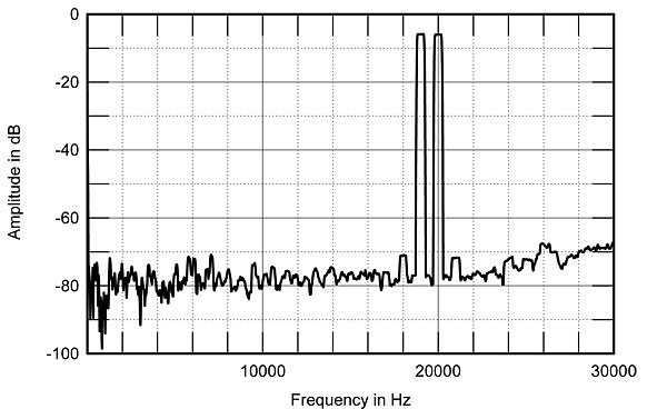
So, where is the 1KHz IM product? It is actually there if you look close enough, it is near the beginning of the Graph and of similar level as the 3rd order sidebands (~ -70dB).
Why does it look different to what Simulators show? Well, simulators lie outrageously about transistor linearity, Ft etc, real transistors in real circuits are usually much worse than simulations.
Also, this Amplifier uses degeneration in the IPS and VAS Stage, lowish open loop gain and PI compensation instead of Miller compensation. As I said it is BASED on the Hitatchi schematic (two differential amps daisy-chained, second with current mirror load), but it does not slavishly replicate it. The results are as measured.
The design actually has been cloned here on DIYA and was extensively discussed in the context (with the usual suspects loosing no time to dump on it and the attempt to clone it, because it was not exactly a Hitatchi Amp, because it was somewhat similar to a Hitachi Amp and because it had a high pricetag), has been simulated to death at least trice and there are also threads on potential improvements.
For anyone particularly interested in the Amplifier, details of it's design and how it fared in subjective evaluation, the whole Stereophile article is here:
Goldmund Mimesis 8 power amplifier | Stereophile.com
Having heard an Amplifier from this generation (not sure if it was a Mimesis 8 or Mimesis 9 though - I suspect a 9 though) I have to say I liked it by far better than most solid state amplifiers I had the chance to hear. It is one of the few SS Amplifiers I'd be willing to live with.
It way bettered big ML Monoblocks we had for comparison in all areas but it played second fiddle to an open-loop tube amplifier (845 Single Ended), so personally I'd probably take a Kondo Ongaku or Baransu if I could have ANY Amp I liked but only one.
Speakers during this evaluation where quite high efficiency I might add (15" PHL Woofer & 2" Compression Driver/Horn giving around 98dB/W/m), which does play a role.
Ciao T
here a REAL 100W Lateral Mosfet Amp based on the hitatchi schematics measured in stereophile with 20V P-P (that is at 10dB lower power than your simulation) into 8 Ohm:
So, where is the 1KHz IM product? It is actually there if you look close enough, it is near the beginning of the Graph and of similar level as the 3rd order sidebands (~ -70dB).
Why does it look different to what Simulators show? Well, simulators lie outrageously about transistor linearity, Ft etc, real transistors in real circuits are usually much worse than simulations.
Also, this Amplifier uses degeneration in the IPS and VAS Stage, lowish open loop gain and PI compensation instead of Miller compensation. As I said it is BASED on the Hitatchi schematic (two differential amps daisy-chained, second with current mirror load), but it does not slavishly replicate it. The results are as measured.
The design actually has been cloned here on DIYA and was extensively discussed in the context (with the usual suspects loosing no time to dump on it and the attempt to clone it, because it was not exactly a Hitatchi Amp, because it was somewhat similar to a Hitachi Amp and because it had a high pricetag), has been simulated to death at least trice and there are also threads on potential improvements.
For anyone particularly interested in the Amplifier, details of it's design and how it fared in subjective evaluation, the whole Stereophile article is here:
Goldmund Mimesis 8 power amplifier | Stereophile.com
Having heard an Amplifier from this generation (not sure if it was a Mimesis 8 or Mimesis 9 though - I suspect a 9 though) I have to say I liked it by far better than most solid state amplifiers I had the chance to hear. It is one of the few SS Amplifiers I'd be willing to live with.
It way bettered big ML Monoblocks we had for comparison in all areas but it played second fiddle to an open-loop tube amplifier (845 Single Ended), so personally I'd probably take a Kondo Ongaku or Baransu if I could have ANY Amp I liked but only one.
Speakers during this evaluation where quite high efficiency I might add (15" PHL Woofer & 2" Compression Driver/Horn giving around 98dB/W/m), which does play a role.
Ciao T
If you live in a free country you may believe whatever you wish. Nature, including electronic amplifiers, will do what she has always done whatever we believe.wahab said:What i believe is that more linearity at 1KHZ will not reduce
the 1KHZ byproduct since it is produced by a lack of linearity at 20KHZ.
I did not say "more linearity at 1kHz". I said more loop gain at 1kHz. Non-linearity at the original frequencies generates the extra components; feedback at the resultant frequencies suppresses the extra components.
I don't wish to repeat an argument already carried out in another thread. If you weren't convinced then you are unlikely to be convinced now. All I was trying to do was show that your criticism of Thorsten's plot is based on your misunderstanding of how feedback works.
All I was trying to do was show that your criticism of Thorsten's plot is based on your misunderstanding of how feedback works.
That s quite an acrobatic claim...
Moreover , if we look at the Goldmund s IMD graph , wich according
to Thorson is a measurement at 20V PP ,that is 7V RMS , we can see
that at 1KHZ there s nothing else than a notch and the close peaks
are not distinguished from noise.
To assert the presence of 1KHZ residual there should be peaks
comparable to the 18 and 21KHZ ones , that is the peaks have two clear bars
with a minimum of width between them.
Anyway, the output level allow the amp to stay in a better linearity zone,
albeit the 18/21khz products are high for a so called high end amplifier.
- Status
- Not open for further replies.
- Home
- Member Areas
- The Lounge
- Sound Quality Vs. Measurements