Hi,
Well, the Philips TDA1541A from the late 1990's taiwan production run measure by far more consistent and indeed lower noisefloor than earlier examples. In our CD-Players late production TDA1541A measure better than early double crown TDA1541A (mostly I think because we eliminate several additional factors that relate certain tolerances in the DAC Chips.
Also, modern PNP Transistors on chip are much better, modern PNP's in general are getting quite good and complementary to NPN actually, compared to the early 80's...
Noisier, interesting.
Today it's probably possible to produce very clean, quality wafers, but it's also possible, that older, cheaper wafer technology is still in use (for cheap chips or ... for counterfeits).
Hi,
I can do this pretty much with a tube Amp, using modest feedback (around 26dB enclosing an output stage with additional local feedback and feedback to the driver stage, input stage open loop) if I can dial back to maybe 85 or 90% of reasonably hard clipping voltage.
I have made quieter 300B SE Poweramp's, if that is re. rated output power, including "below 100Hz"... The tube amp referenced re. THD probably also managed this level of noise. I used to run it on 98dB/2.83V/1m sensitive speakers without noise being audible with your ear next to the cone...
Without noise being audible to the ear this way,
your amp can also be used for dynamic headphones,
or for electrostatic headphones (with connectors before the output transformer).
Hi,
I have measured expensive high end solid state amp's that measured worse than what you note as well...
Probably with huge gain, highpower amps.
My FFT osco just shows 65dB usable dynamic range
(without suppressed carrier), so I have to measure
near clipping to see the harmonics (k2, k3, k4,...).
Regards,
It is worth sometimes, as a reality-check to consider the noise-floor and distortion of recording microphones as well as the distortion and maximum SPL of Hifi and High End Speakers and to consider at what peak SPL's we listen and what peak SPL's are the microphones position.
Mic distortion figures are very hard to find, can you point us to some? These guys seem to think its around .01%
Schoeps and other pro mic distortion - Gearslutz.com
As for mic noise, it is rarely heard over the room noise, and preamp noise (except for ribbons) unless your recording whispering from 2 meters away.
As part of this paper he computes capsule distortion geometriclly, it would give you a ballpark estimate. (free download from B&K)
Reduction of Non-linear Distortion in
Condenser Microphones by Using
Negative Load Capacitance
by Erling Frederiksen
Thanks Scott. Unfortunatley the only distortion figures I saw were for SPLs over 140db (.5%). I would like to know what they are at more typical levels. Do we have to use the statement
and conclude 20db less SPL means 20db less distortion?
(and how do you make a test sound with that little distortion?)
At high levels it is generally limited by non- linear distortion which is proportional to the sound pressure and is produced by the microphone itself
and conclude 20db less SPL means 20db less distortion?
(and how do you make a test sound with that little distortion?)
Thanks Scott. Unfortunatley the only distortion figures I saw were for SPLs over 140db (.5%). I would like to know what they are at more typical levels. Do we have to use the statement
and conclude 20db less SPL means 20db less distortion?
(and how do you make a test sound with that little distortion?)
From the tables even at huge SPL the thirds are small. For a weakly non-linear system the seconds would go down at twice the rate (-20dB fundamental, -40dB 2nds). So it looks like .01% at low levels is possible. They infer the distortion from a two tone test, using two speakers and care in keeping the IM only from the mic. I have seen this used in the industry, and it makes intuitive sense that the mic can't be greater than the residual unless there is some strange cancellation. OTOH their result for the high frequencies being worse is counter intuitive since the displacements have dropped? This is out of my expertise at this point.
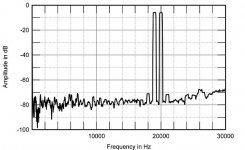
IM test signal (19k + 20k).
With an horizontal linear scale that start at 10KHZ...

Seems that they didnt understand that the main interest was to
see byproducts at 1KHZ...
Anyway , that was enough of a numbered exemple for Thorsten...
IM test signal (19k + 20k).
Err. OK, but why the sudden rise at 20K ...what is this telling us ?
Hi,
Need glasses? The linear scale starts at 0Hz...
Seems they use the kind of measurements common at the time (over 20 years ago) and the 1KHz product would show up.
If you do not like the way others measure, why don't show some actual measurements of your own (not that they actually per se matter BTW)?
Ciao T
With an horizontal linear scale that start at 10KHZ...
Need glasses? The linear scale starts at 0Hz...
Seems that they didnt understand that the main interest was to see byproducts at 1KHZ...
Seems they use the kind of measurements common at the time (over 20 years ago) and the 1KHz product would show up.
Anyway , that was enough of a numbered exemple for Thorsten...
If you do not like the way others measure, why don't show some actual measurements of your own (not that they actually per se matter BTW)?
Ciao T
Hi,
The "sudden rise at 20KHz" IS the signal.
The signal in this test uses equal levels of 19KHz and 20KHz signals, giving a second order product at 1KHz which is easy to quantify and loads of higher order rubbish that is a bit harder to account for.
BTW, "intermodulation distortion" implies two signals to intermodulate across a non-linear system, you cannot measure IMD with a single frequency signal.
Ciao T
Err. OK, but why the sudden rise at 20K ...what is this telling us ?
The "sudden rise at 20KHz" IS the signal.
The signal in this test uses equal levels of 19KHz and 20KHz signals, giving a second order product at 1KHz which is easy to quantify and loads of higher order rubbish that is a bit harder to account for.
BTW, "intermodulation distortion" implies two signals to intermodulate across a non-linear system, you cannot measure IMD with a single frequency signal.
Ciao T
What graph are you looking at? The one posted by Thorsten shows DC=>30KHz.With an horizontal linear scale that start at 10KHZ...
Seems that they didnt understand that the main interest was to
see byproducts at 1KHZ...
Anyway , that was enough of a numbered exemple for Thorsten...
Attachments
T, H&H is almost 1/2 the size of my 'Radiotron Designers Handbook' or 'The Scientific Papers of James Clerk Maxwell'. (Try that one on for size).
Seriously, I think the H&H is a good book for the technical educated person without much electronic design experience. It is accurate, up-to-date, and readable.
Seriously, I think the H&H is a good book for the technical educated person without much electronic design experience. It is accurate, up-to-date, and readable.
My 'strong' recommendation is to: Google '2n2222 motorola data sheet' Get the long form with graphs. It can be a learning experience, often ignored today.
H.H., I'll check that book out when I think I understand the first two.
I only ever used the 2222 and 2907 for things like switching reed relays and LED drivers. Too many people I guess are used to the databook application example and never read the specs. I doubt that was the case in this design, more like what the accountant allowed. It was used for the bias spreader, so I suspect higher current and cheap were his criteria.
The part of the DH-120 I do not understand at all yet is the function or R10. I am guessing it is assisting in PSRR. It has about 100V across it and dissipates 1.9W. (It was a 5.1K 2W part, and singed the boards. I put in a 3W on longer leads) So, this stack of diodes that manage the constant current source and cascode bias is pulling 20mA rail to rail. Does the higher current through the diodes cause them to be more stable?
Ah, my HCA1200ii just got here. I hope it is rugged as it took a whack or two. The rack mount on one side is bent way back. It was loose in the box.
Somebody won't get a five star rating.Tvr, I believe that this 'obsolete' device is so well known is because it was easy to model in the early SPICE days, when they needed devices with extensive published measurements to compare against.
Is R10 across the filter caps? If so, it is a BLEED resistor, so that when you unplug the amp, it will not retain power supply voltage for a long time.
Is R10 across the filter caps? If so, it is a BLEED resistor, so that when you unplug the amp, it will not retain power supply voltage for a long time.
John,
I do recommend the RDH in the thread in tubes. Maxwell's collections is way heavy.
I agree completely.
BUT, I'd really not try to read it cover to cover or throw it out of windows high up in tower blocks in frustration if trying.
But yes, for the basic facts on electronics H&H are not a bad place.
Ciao T
T, H&H is almost 1/2 the size of my 'Radiotron Designers Handbook' or 'The Scientific Papers of James Clerk Maxwell'. (Try that one on for size).
I do recommend the RDH in the thread in tubes. Maxwell's collections is way heavy.
Seriously, I think the H&H is a good book for the technical educated person without much electronic design experience. It is accurate, up-to-date, and readable.
I agree completely.
BUT, I'd really not try to read it cover to cover or throw it out of windows high up in tower blocks in frustration if trying.
But yes, for the basic facts on electronics H&H are not a bad place.
Ciao T
Hi,
I think the other way around may be more use...
It may not be in the rules, but much of the more advanced discussion here and much in the books of Cordell & Self takes H&H "as read"...
Ciao T
H.H., I'll check that book out when I think I understand the first two.
I think the other way around may be more use...
It may not be in the rules, but much of the more advanced discussion here and much in the books of Cordell & Self takes H&H "as read"...
Ciao T
The DH 120 did not have bleeder caps. When I put in the new ones, I added some.
No, this sits between the diodes used to bias the ccs and cascode. It will bled the main caps, but I can't imagine that was his intent.
Hafler - Tech Support
Rockford is nice enough to publish their documentation.
No, this sits between the diodes used to bias the ccs and cascode. It will bled the main caps, but I can't imagine that was his intent.
Hafler - Tech Support
Rockford is nice enough to publish their documentation.
- Status
- Not open for further replies.
- Home
- Member Areas
- The Lounge
- Sound Quality Vs. Measurements