Hi,
As I always say, GND isn't.
My gainclone does use a different reference, however it uses extra PSU filtering (CRC Pi-Filters), which also helps, plus my special local decoupling...
Yes, I understand this.
In my case I explicitly did not want to make a "super gainclone", but something for a "reality check".
Ciao T
Try referencing everthing to the neg rail instead of GND,
As I always say, GND isn't.
My gainclone does use a different reference, however it uses extra PSU filtering (CRC Pi-Filters), which also helps, plus my special local decoupling...
if you look at the PSRR and CMRR plots you'll instantly see why...
Yes, I understand this.
In my case I explicitly did not want to make a "super gainclone", but something for a "reality check".
Ciao T
Hi,
My Gainclone is 40W + 40W and it is a straight DC design. Incidentally, the PSU is a big torroidal transformer and two pairs of 3,300uF/50V Elna Silmic II caps in CRC.
It is a "straightline integrated", british style, input selection (relay), 50K Alps Blue Volume Control, direct to the output Amp, LM3875 with more Elna Silmic II, and baked/burned in/selected/mateched AB Carbon composition resistors.
I keep this one around as "reality-check" any amp that is not at least the equal of this humble little Amp in all areas is basically junk. The one thing it does not is unlimited power, drive super low impedances or stunt-bass.
But everything else it does on a very high level. The number of amplifiers that did a lot worse than this little "reality check" is surprisingly large.
Ciao T
Fine, but when? In 2005? That's merely 25 years after they stopped making that model of Maranz power amp.
Also, as you yourself pointed out, a powerhouse it isn't - whereas the Maranz could be said to be approaching one.
For a start, they were the usual damn liars of the time. Under the specified condition, it actually does better in literally all departments after refreshing. It drove my AR94 without a hitch, with never an indication that they were struggling.
And it (170 DC) did very well indeed with my friend's Apogees, a boast very few amps can make.
While this speaks well of Marantz' technology and know-how, much more imporatnt than the sheer power is the fact that it maintains its posture and overall composed sound right up to its top.
I should also add that this particular model, as well as some other models of theirs which are held in high regard and fetch the best prices today were made in the 1978-1980 period. Looking back, one will easily see that the other big names of that time were also producing what was probably their best in regular production (not some special models, special series). I imply such companies as Sansui, Kenwood/Trio, Pioneer, Onkyo, Yamaha, etc. In many ways, that could be called their golden period. It was just after 1980 that the video craze caught on, with the PC following soon after, when audio took first the back seat, and then stepped out of the public imagination's eye by 1982 or 1983, when enough IBM PCs were already around, and the first clones began to appear in significant numbers from Compaq, Olivetti, UK's Apricot, etc.
There's a season for everything. That was the pinnacle for Marantz, the last series designed in the U.S.A. and manufactured in Japan. After that, it progressively became more and more a purely Japenese company, until it became just one more kid on the block, losing what made it special. Their very clever circuitry soon gave way to simplistic circuits which cost less, very alike to other Japanese products of the day, and with a similar sound. That just wasn't the real thing any more.
Hi,
I build stuff based around the east german copies of the TDA2030 and 2040 in the 80's. While not explicitly made as DC Amp I used them that way.
Making a DC coupled Amp is trivial and has been for many decades.
Not sure if that "could be said". Mine was not designed as powerhouse, but if you want to drive very low loads you can use external transistors (the precise circuit John Curl showed for the Headphone Amp in his Blowtorch Thread "MK II").
To me it matters more that sounds good "down to the bottom", though I like stuff that goes to 11. If it goes to 11 but is bad at 1-10, I could not care less.
And I'd rather trade a good 7 for a bad 11...
This we agree upon.
The top of the line stuff by Japanese Majors from the late 70's to around the Early 80's stands up to almost anything out there, given decent condition and loving maintainance. It was downhill from there, though we seem to be seeing a bit of a Renaissance (or just the dead cat bounce).
Ciao T
Fine, but when? In 2005?
I build stuff based around the east german copies of the TDA2030 and 2040 in the 80's. While not explicitly made as DC Amp I used them that way.
Making a DC coupled Amp is trivial and has been for many decades.
Also, as you yourself pointed out, a powerhouse it isn't - whereas the Maranz could be said to be approaching one.
Not sure if that "could be said". Mine was not designed as powerhouse, but if you want to drive very low loads you can use external transistors (the precise circuit John Curl showed for the Headphone Amp in his Blowtorch Thread "MK II").
much more imporatnt than the sheer power is the fact that it maintains its posture and overall composed sound right up to its top.
To me it matters more that sounds good "down to the bottom", though I like stuff that goes to 11. If it goes to 11 but is bad at 1-10, I could not care less.
And I'd rather trade a good 7 for a bad 11...
I should also add that this particular model, as well as some other models of theirs which are held in high regard and fetch the best prices today were made in the 1978-1980 period. Looking back, one will easily see that the other big names of that time were also producing what was probably their best in regular production (not some special models, special series). I imply such companies as Sansui, Kenwood/Trio, Pioneer, Onkyo, Yamaha, etc. In many ways, that could be called their golden period.
This we agree upon.
The top of the line stuff by Japanese Majors from the late 70's to around the Early 80's stands up to almost anything out there, given decent condition and loving maintainance. It was downhill from there, though we seem to be seeing a bit of a Renaissance (or just the dead cat bounce).
Ciao T
Tom,
Pro's :
Con's :
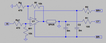
In fact I'm using something like a 24V/3W lamp for R1, that catches a couple of things well. Output snubber also goes to the neg rail. It can be used for multiple channels without effort.
The circuit is useful for insight on what decoupling really is about.
Basically it is a single supply amp, but the output cap is inside the feedback and is not charged to mid-supply through the load. The mid-supply reference is derived from and used at the back end of the amp, not the front end.
I'll try to post a full-blown example amp (P2P style) in the chip amps forum some time.
Pro's :
- Circuit input and output AC-referenced to the same point than the chip's internals, the negative rail.
- The remaining little ripple voltage on the opamp input vs reference is fully linear correlated to load current vs. a chopped copy + PSU ripple. And no PSU noise here.
- Supply and load ripple runs pretty much into the void on the positive rail, which has much better PSRR.
- DC-coupled, no output capacitor (as it INSIDE the full feedback).
- Also works with true single rail, with only little compromise (R1 mutates into half-supply resistor divider then).
Con's :
- Can't sustain long term DC or extremely LF signals or large chip voltage offsets, resulting in more than a few mA, otherwise the midpoint shifts (a voltage drop along R1) until balanced is restored -- well that's a pro as well, DC protection.
- Can't be used with speaker which don't have a DC path. Output saturates to a rail without a load connected.
- Need some protection, especially for power down, for both the speaker and chip. One diode from GND to chip PWR+ does the most important thing.
- Needs higher voltage caps, or series connected ones (with bleeders/stabilizers).
In fact I'm using something like a 24V/3W lamp for R1, that catches a couple of things well. Output snubber also goes to the neg rail. It can be used for multiple channels without effort.
The circuit is useful for insight on what decoupling really is about.
Basically it is a single supply amp, but the output cap is inside the feedback and is not charged to mid-supply through the load. The mid-supply reference is derived from and used at the back end of the amp, not the front end.
I'll try to post a full-blown example amp (P2P style) in the chip amps forum some time.
Last edited:
I get by with 50-ish solid state because I have a 4th order electronic crossover at 80 Hz. I don't play things terribly loud, which maybe why we both still have our hearing.
The cheap amp was to get a chassis to play with. It is total doo-doo, but served quite well to understand tube amps. Funny how we demand power. My dad had the giant powerhouse of the day, a 30W Allied to drive his AR-2. Unheard of at the time. I guess the Dynas broke that barrier.
The cheap amp was to get a chassis to play with. It is total doo-doo, but served quite well to understand tube amps. Funny how we demand power. My dad had the giant powerhouse of the day, a 30W Allied to drive his AR-2. Unheard of at the time. I guess the Dynas broke that barrier.
Hi,
I basically use this concept for the capacitors local to the individual LM3875 in my Gainclone, with 220uF Silmic Cap's and various Film Cap's as bypass/snubber.
The main PSU section is traditional symmetrical, rectifier -> 2 * 3,300uF -> tripple 0.235 Ohm resistors -> 3,300uF forming a 200Hz lowpass, incidentally. Rails are around +/- 32V without load, 320VA torroidal transformer.
Incidentally, power levels are comparable to my Tube Amp, which is not DC coupled and does not use looped feedback, but subjectively sounds notably better than the Gainclone.
My "big" Vincent Solid State Amp with 180WPC comes in a distance third on sound quality, except raw power, which is why it will have heck modified out of it, so hopefully it will no longer sound like the amp from Krell, ooops, Hell...
Ciao T
FWIW, see pic for my take on that neg-rail referenced super-CG, showing the concept. There are gotcha's, as usual.
I basically use this concept for the capacitors local to the individual LM3875 in my Gainclone, with 220uF Silmic Cap's and various Film Cap's as bypass/snubber.
The main PSU section is traditional symmetrical, rectifier -> 2 * 3,300uF -> tripple 0.235 Ohm resistors -> 3,300uF forming a 200Hz lowpass, incidentally. Rails are around +/- 32V without load, 320VA torroidal transformer.
Incidentally, power levels are comparable to my Tube Amp, which is not DC coupled and does not use looped feedback, but subjectively sounds notably better than the Gainclone.
My "big" Vincent Solid State Amp with 180WPC comes in a distance third on sound quality, except raw power, which is why it will have heck modified out of it, so hopefully it will no longer sound like the amp from Krell, ooops, Hell...
Ciao T
Folks,
So I posted and found the design simmed and criticised by others... I made some changes and got fed up with working in the "pen, paper, slipstick" domain.
I recently found the latest update of Tina-Ti included more devices and stuff, so rather then spending time in LTSpice, I assigned some moderately close devices found readily in Tina-Ti, to get a basic idea. Tina-Ti has various areas where results are either seriously funky, or their display is funky. It is necessary to discount/adjust for this. For example it's Fourier shows a "constant height grass" growing at higher harmonics if general HD is low, this seems a process artefact, as other simulators and reality beg to differ.
There are considerable differences between the modelled devices (which all seem to be 1960's/1970's devices - going as far as forcing me to use TIP33/34 as Outputs and IRF610/9610 as Drivers). So some devices ended up worse, others possibly better than what is on the page.
For example, the drivers in the Sim have way more Crss than the actual devices, but they have less than halve the output impedance too, the J-Fets have a touch more capacitance and transconductance.
So the simulation results should be taken "cum grano salis magnitudinem montis". I attach the current schematic, including the final DC nulling circuit (which combines very low gain servo and trick circuitry to get low offset and low sonic footprint).
Anyway, simming cascodes convinced me that even heavily degenerated VAS benefit from cascoding. The added complexity of cascoded VAS vs. Parallel VAS is modest. So Hawksford cascoded, J-Fet buffered push-pull VAS it is. That said, I'd not loose excessive sleep without cascode.
In fact, the circuit uses many features that are also shown to reduce circuit thermal memory, but as feedback is low, memory distortion is minimised anyway.
I did most of my investigation with 50KHz sines and squares, adding 10Khz and 1KHz tests for completeness.
I also simmed the same circuit as 16dB Gain line stage (see the High End Tone Control Thread to see what circuit that will drop in) as well. This means a joined shunt regulated +/-60V supply and no BJT outputs, just a pair of Fets.
Overall I am reasonably happy with the results.
The Linestage sims at < 0.001% THD (H2 dominant ~ 10dB+ above the rest) for around 12V / 50KHz into 10K//1nF load. I guess the sim is overly enthusiastic, given only 36dB NFB, or maybe not... I guess time to drop the open loop gain...
Other measurements are way past good or bad.
The Poweramp sims as 0.1% THD (H3 dominant) for 26V / 50KHz into 8Ohm with 14dB global NFB. For reference, the 1KHz result is around 0.03% (equal H2/H3) for 26V/8Ohm.
Anyway, these two observations illustrate that most of the distortion in the Poweramp derives from the output stage.
Additionally, with the filter on the input and the antique (1968) TIP33/34 in the output stage (with 3MHz Ft vs the more modern transistors with 30MHz Ft) the 50KHz square-wave suggests > 75V/uS slew rate, I suspect with much lower capacitance from the lateral driver Fet's and much higher FT for the output transistors the real HF distortion and slew rate will be much better.
Given the parts models used and the real parts that will be used I am quite happy with the simmed results.
Ciao T
FWIW, here my take on what to implement in a nice case, with a pair of 0.3K/W heatsinks and a 1200VA mains transformer...
...
PS, the attachment has not been build or tested (yet), but is intended to be implemented to some existing hardware, using existing PCB's and as many existing parts as possible, while getting something more to my liking.
So I posted and found the design simmed and criticised by others... I made some changes and got fed up with working in the "pen, paper, slipstick" domain.
I recently found the latest update of Tina-Ti included more devices and stuff, so rather then spending time in LTSpice, I assigned some moderately close devices found readily in Tina-Ti, to get a basic idea. Tina-Ti has various areas where results are either seriously funky, or their display is funky. It is necessary to discount/adjust for this. For example it's Fourier shows a "constant height grass" growing at higher harmonics if general HD is low, this seems a process artefact, as other simulators and reality beg to differ.
There are considerable differences between the modelled devices (which all seem to be 1960's/1970's devices - going as far as forcing me to use TIP33/34 as Outputs and IRF610/9610 as Drivers). So some devices ended up worse, others possibly better than what is on the page.
For example, the drivers in the Sim have way more Crss than the actual devices, but they have less than halve the output impedance too, the J-Fets have a touch more capacitance and transconductance.
So the simulation results should be taken "cum grano salis magnitudinem montis". I attach the current schematic, including the final DC nulling circuit (which combines very low gain servo and trick circuitry to get low offset and low sonic footprint).
Anyway, simming cascodes convinced me that even heavily degenerated VAS benefit from cascoding. The added complexity of cascoded VAS vs. Parallel VAS is modest. So Hawksford cascoded, J-Fet buffered push-pull VAS it is. That said, I'd not loose excessive sleep without cascode.
In fact, the circuit uses many features that are also shown to reduce circuit thermal memory, but as feedback is low, memory distortion is minimised anyway.
I did most of my investigation with 50KHz sines and squares, adding 10Khz and 1KHz tests for completeness.
I also simmed the same circuit as 16dB Gain line stage (see the High End Tone Control Thread to see what circuit that will drop in) as well. This means a joined shunt regulated +/-60V supply and no BJT outputs, just a pair of Fets.
Overall I am reasonably happy with the results.
The Linestage sims at < 0.001% THD (H2 dominant ~ 10dB+ above the rest) for around 12V / 50KHz into 10K//1nF load. I guess the sim is overly enthusiastic, given only 36dB NFB, or maybe not... I guess time to drop the open loop gain...
Other measurements are way past good or bad.
The Poweramp sims as 0.1% THD (H3 dominant) for 26V / 50KHz into 8Ohm with 14dB global NFB. For reference, the 1KHz result is around 0.03% (equal H2/H3) for 26V/8Ohm.
Anyway, these two observations illustrate that most of the distortion in the Poweramp derives from the output stage.
Additionally, with the filter on the input and the antique (1968) TIP33/34 in the output stage (with 3MHz Ft vs the more modern transistors with 30MHz Ft) the 50KHz square-wave suggests > 75V/uS slew rate, I suspect with much lower capacitance from the lateral driver Fet's and much higher FT for the output transistors the real HF distortion and slew rate will be much better.
Given the parts models used and the real parts that will be used I am quite happy with the simmed results.
Ciao T
Attachments
Last edited:
Hi,
I basically use this concept for the capacitors local to the individual LM3875 in my Gainclone, with 220uF Silmic Cap's and various Film Cap's as bypass/snubber.
The main PSU section is traditional symmetrical, rectifier -> 2 * 3,300uF -> tripple 0.235 Ohm resistors -> 3,300uF forming a 200Hz lowpass, incidentally. Rails are around +/- 32V without load, 320VA torroidal transformer.
Incidentally, power levels are comparable to my Tube Amp, which is not DC coupled and does not use looped feedback, but subjectively sounds notably better than the Gainclone.
My "big" Vincent Solid State Amp with 180WPC comes in a distance third on sound quality, except raw power, which is why it will have heck modified out of it, so hopefully it will no longer sound like the amp from Krell, ooops, Hell...
Ciao T
Vincent's are no Krell , there maybe hell to pay thou , trying for good sound ..
...but as feedback is low, memory distortion is minimised anyway.
kinda at odds with every application of Bode Sensitivity analysis, feedback amp theory I've learned - thermal/memory distortion is best alleviated with high global feedback
only the common mode input diff pair power modulation is "outside" the feedback - and high global feedback reduces the diff signal pwr to uW making matching highly effective
still the bootstrapped cascode of the diff pair Q is a good idea to reduce amp input Z nonlinearity
Last edited:
Question about constant current sources. So I don't double post,
http://www.diyaudio.com/forums/solid-state/209764-best-vas-7.html#post2969161
Any comments on experience with the resulting sonics would be appreciated.
http://www.diyaudio.com/forums/solid-state/209764-best-vas-7.html#post2969161
Any comments on experience with the resulting sonics would be appreciated.
Hi,
You are right, thanks heaven.
Their sound only contains a modest trace of this most objectionable (to me) sound quality of all. They are nowhere near as bad as the real thing. All the worst Solid State Amplifiers I had the misfortune to hear have a Naim starting with "K".
There is one thing the Amplifiers starting with "K" do well, that is artificial, steroid pumped, makes Arnold S from the Conan Days look like a wimp stunt bass. All else gets mangled beyond sense...
I had to endure a show where the main system used of these Amplifiers with a name starting with "K". It want not as bad the East German Stasi Submarine, but the differences where minor. Staying in the room with this system playing for more than 10 minutes took major effort.
Note, not all amplifier manufacturers starting with K produce that sound, but two I know very well (they even have similar logo's) do...
Ciao T
Vincent's are no Krell
You are right, thanks heaven.
Their sound only contains a modest trace of this most objectionable (to me) sound quality of all. They are nowhere near as bad as the real thing. All the worst Solid State Amplifiers I had the misfortune to hear have a Naim starting with "K".
There is one thing the Amplifiers starting with "K" do well, that is artificial, steroid pumped, makes Arnold S from the Conan Days look like a wimp stunt bass. All else gets mangled beyond sense...
I had to endure a show where the main system used of these Amplifiers with a name starting with "K". It want not as bad the East German Stasi Submarine, but the differences where minor. Staying in the room with this system playing for more than 10 minutes took major effort.
Note, not all amplifier manufacturers starting with K produce that sound, but two I know very well (they even have similar logo's) do...
Ciao T
Hi,
Thermal memory presents an error signal that is outside the loop for the IPS (not just common mode) and can reach levels that are comparable to the IPS error signal with high levels of global looped feedback.
Local degeneration also acts against thermal memory distortion and with the same effectiveness, yet overall in the closed multi-state loop, any resultant impact of thermal memory is minimised as it becomes small next to error signal.
Ciao T
kinda at odds with every application of Bode Sensitivity analysis, feedback amp theory I've learned - thermal/memory distortion is best alleviated with high global feedback
Thermal memory presents an error signal that is outside the loop for the IPS (not just common mode) and can reach levels that are comparable to the IPS error signal with high levels of global looped feedback.
Local degeneration also acts against thermal memory distortion and with the same effectiveness, yet overall in the closed multi-state loop, any resultant impact of thermal memory is minimised as it becomes small next to error signal.
Ciao T
In fact, the circuit uses many features that are also shown to reduce circuit thermal memory, but as feedback is low, memory distortion is minimised anyway.
To the contrary , the more the NFB the less the instantaneous
linearity variations , among others the thermal variation dependant caracteristics.
There s a lot of stages in your amp, and this invariably
increase phase shift wich will mandate heavy degeneration to reduce
global transconductance , to a point that there will be no benefit
in pursuing this path.
Anyway, these two observations illustrate that most of the distortion in the Poweramp derives from the output stage.
Once you really understand this, you ll focus on improving
global linearity.....
Hi,
Really. Closed loop - yes. Is that what matters most?
Actually, there are two gain stages in my Amp. All other (buffer) stages are included precisely to counteract bandwidth and linearity limitations, arising from non-ideal transistor behaviour.
So, they do not introduce phaseshift, they reduce it. It is called broad-banding a circuit, generally the lower the source impedance for a bipolar transistor the wider the bandwidth (and the lower the attendant phaseshift) and the lower the distortion.
First, the heavy degeneration is one of the main design "features", not a side-effect. Secondly, what benefits do you expect from persuing a different path (you may remember that there is zero proof that very low THD improves sound quality)?
I have not interest to improve what you call global linearity beyond certain minimal requirements. There is no evidence that doing so provides any tangible benefits.
Once you understand that you may be able to focus on things that actually matter.
Ciao T
To the contrary , the more the NFB the less the instantaneous linearity variations , among others the thermal variation dependant caracteristics.
Really. Closed loop - yes. Is that what matters most?
There s a lot of stages in your amp, and this invariably increase phase shift
Actually, there are two gain stages in my Amp. All other (buffer) stages are included precisely to counteract bandwidth and linearity limitations, arising from non-ideal transistor behaviour.
So, they do not introduce phaseshift, they reduce it. It is called broad-banding a circuit, generally the lower the source impedance for a bipolar transistor the wider the bandwidth (and the lower the attendant phaseshift) and the lower the distortion.
wich will mandate heavy degeneration to reduce
global transconductance , to a point that there will be no benefit
in pursuing this path.
First, the heavy degeneration is one of the main design "features", not a side-effect. Secondly, what benefits do you expect from persuing a different path (you may remember that there is zero proof that very low THD improves sound quality)?
Once you really understand this, you ll focus on improving global linearity.....
I have not interest to improve what you call global linearity beyond certain minimal requirements. There is no evidence that doing so provides any tangible benefits.
Once you understand that you may be able to focus on things that actually matter.
Ciao T
Last edited:
Thorsten, thanks for posting this. I am trying to figure out how the DC servo works but I might not quite get it. The there is no DC feedback over the servo opamp, so that at DC it is open loop. Wouldn't it be better to limit it's DC-gain by placing a resistor in parallel to the cap? Or am I missing something,
vac
vac
Hi,
The best to imagine the servo is to consider the capacitors first as resistors. In this case an inverting Op-Amp is in the Feedback loop of the servo and thus the servo is non-inverting. Any Voltage on the output of the inverting main amp is amplified by the Servo Op-Amp and then re-injected into the inverting input of the Op-Amp. This will oppose any change of the output voltage of the main amplifier.
Now we add the capacitors back.
Above a certain AC frequency, the capacitors will have a very low impedance, yet the DC resistance is basically infinity. So for DC the circuit of the amplifier has a gain of 1. For AC the gain is around 20.
As the input section does not use monolithic pairs and the input fets (as well as the VAS Buffers and driver laterals) are not necessarily matched, we still get potentially quite a bit of offset, especially given the amplifiers relatively low DC Gain (a little over 50dB). Hence the servo is added to null out this offset.
The fact that we inject the servo output through 4.7MOhm into the inverting input where the impedance to ground is around 470 Ohm (assuming the capacitors in the main amplifiers feedback network are shorted) means the output from the servo is attenuated by around 80dB. Another way to view this is to say that the signal from the servo passes through a first order 0.01Hz lowpass, with a Zero at around 16Hz, thus giving a PI regulator behaviour.
The servo itself is differential and has 0.16Hz cutoff. It means at 0.16Hz the gain of the circuit is only 3dB above unity and the input filter will attenuatre 3dB. So at 16Hz the servo itself will filter any signal from the main Amp by 40dB, so the AC on the servo output for a full 50V peak swing becomes 0.5V. This as remarked is then attenuated a further 80dB due to the way the servo signal is injected into the inverting input.
Meanwhile DC will be amplified by the full DC gain of our Op-Amp (OPA-627), that is by 120dB. The DC Gain for the injected signal is around 0.2, we we retain over 100dB DC Loop gain. This gain of the servo Amp charges the capacitor in the Servo Amp feedback progressively, while shifting the output of the Op-Amp, which in turn charges the capacitors in the Amplifiers feedback loop.
This in turn causes the DC voltage appearing on the output of the Amplifier to be reduced. Eventually the system will reach an equilibrium. As we are dealing with a total 2nd Order filter in a loop we have potential for instability, so I will have to do a sim for that to check.
Ciao T
I am trying to figure out how the DC servo works but I might not quite get it. The there is no DC feedback over the servo opamp, so that at DC it is open loop. Wouldn't it be better to limit it's DC-gain by placing a resistor in parallel to the cap? Or am I missing something
The best to imagine the servo is to consider the capacitors first as resistors. In this case an inverting Op-Amp is in the Feedback loop of the servo and thus the servo is non-inverting. Any Voltage on the output of the inverting main amp is amplified by the Servo Op-Amp and then re-injected into the inverting input of the Op-Amp. This will oppose any change of the output voltage of the main amplifier.
Now we add the capacitors back.
Above a certain AC frequency, the capacitors will have a very low impedance, yet the DC resistance is basically infinity. So for DC the circuit of the amplifier has a gain of 1. For AC the gain is around 20.
As the input section does not use monolithic pairs and the input fets (as well as the VAS Buffers and driver laterals) are not necessarily matched, we still get potentially quite a bit of offset, especially given the amplifiers relatively low DC Gain (a little over 50dB). Hence the servo is added to null out this offset.
The fact that we inject the servo output through 4.7MOhm into the inverting input where the impedance to ground is around 470 Ohm (assuming the capacitors in the main amplifiers feedback network are shorted) means the output from the servo is attenuated by around 80dB. Another way to view this is to say that the signal from the servo passes through a first order 0.01Hz lowpass, with a Zero at around 16Hz, thus giving a PI regulator behaviour.
The servo itself is differential and has 0.16Hz cutoff. It means at 0.16Hz the gain of the circuit is only 3dB above unity and the input filter will attenuatre 3dB. So at 16Hz the servo itself will filter any signal from the main Amp by 40dB, so the AC on the servo output for a full 50V peak swing becomes 0.5V. This as remarked is then attenuated a further 80dB due to the way the servo signal is injected into the inverting input.
Meanwhile DC will be amplified by the full DC gain of our Op-Amp (OPA-627), that is by 120dB. The DC Gain for the injected signal is around 0.2, we we retain over 100dB DC Loop gain. This gain of the servo Amp charges the capacitor in the Servo Amp feedback progressively, while shifting the output of the Op-Amp, which in turn charges the capacitors in the Amplifiers feedback loop.
This in turn causes the DC voltage appearing on the output of the Amplifier to be reduced. Eventually the system will reach an equilibrium. As we are dealing with a total 2nd Order filter in a loop we have potential for instability, so I will have to do a sim for that to check.
Ciao T
Just one question, Thorsten.
In my experience, the "easiest" way to reduce overall distorion is to degenerate the input stage and to add output devices, so that the work is divided even more.
For the first point, you did it anyway, so that's that. For the second point, in view of your targeted power, why didn't you add another pair (or two) of the output devices? I mean, they are fairly cheap, readily available and time proven. It can't hurt, it may not reduce overall distortion by much, but it will offload the output stage even more and spread the heat dissipation to yet another two points, making your heat sink even more efficient.
Just wondering.
- Status
- Not open for further replies.
- Home
- Member Areas
- The Lounge
- Sound Quality Vs. Measurements