Mostly, yes.benb said:Are speakers usually designed with the assumption they'll be driven only by an amplifier with a high damping factor?
Given the voice coil resistance will be several ohms, a few tenths in the cable will have only a small effect. The main effect is to prove that really high amplifier DFs are pointless, although in themselves harmless.
A current mode amplifier would need to be used with speakers designed for it (i.e. more mechanical damping), unless you like to listen to the bass resonance.
I'd think they should be tested with a range of driving impedances, if for no other reason than to find out what happens.
John Atkinson does measure loudspeaker impedances. And he measures amplifiers with resistive loads and simulated loudspeaker loads. So between those one can get an idea about the loudspeaker/amplifier interactions.
Last edited:
At least in the simulation of th e120, the key to distortion, particularly even, is the value ratio of the gate stoppers. As much as 20dB between the calculated recommended values and what can be done by playing around.
This makes sense to think about it. It also means that decent performance is a matter of hand selecting in-circuit. The recommended values of 470 and 330 are not balanced. 440 and 400 sim to null all even harmonics. It did not like higher values. This was masking everything else I was playing with on the input as those changes were below the outputs distortion by a lot.
This makes sense to think about it. It also means that decent performance is a matter of hand selecting in-circuit. The recommended values of 470 and 330 are not balanced. 440 and 400 sim to null all even harmonics. It did not like higher values. This was masking everything else I was playing with on the input as those changes were below the outputs distortion by a lot.
That would typically cause frequency response variations of 1/2 a decibel or so, depending on the speakers. Whether that's audible and/or objectionable would depend on the listener and the speakers IMHO....but when I insert a 0.46 Ohm resistor
between my amp and speaker (thus lowering the damping factor from
something > 50 to something about 17)...
That would typically cause frequency response variations of 1/2 a decibel or so, depending on the speakers. Whether that's audible and/or objectionable would depend on the listener and the speakers IMHO.
Broad (i.e., low-Q) variations are durable (i.e., survive the passage to "double-blind") in subjective evaluations. Even at that rather remarkably low level. It helps to have trained listeners, indeed.
Hi,
You need to separate two things here.
One is the actual damping (electrical) of the voice coils movement by the source. The other is frequency response. Unless your Speaker is a pure full range driver with no crossover, flat impedance and well controlled LF Peaks you can expect changes in frequency response that are quiet wide ranging. Also, you will alter (lower) the distortions in the speaker by adding series resistance
However, this has nothing to do with electrical damping.
This brings us back to the "system" part. I for example design my speakers such that reasonable levels of source impedance do not cause frequency response shifts (in other words with a flat impedance).
The bottom line is that any given speaker system needs to be designed with a view to what source impedance will be present. While "Zero ohm" is a common convention, in fact many speakers do not work well under these conditions.
Ciao T
I have no reason not to believe you, but when I insert a 0.46 Ohm resistor between my amp and speaker (thus lowering the damping factor from something > 50 to something about 17) the difference in the bass region is _very_ clearly audible. How can this be the case if it´s never more than 2 ?
You need to separate two things here.
One is the actual damping (electrical) of the voice coils movement by the source. The other is frequency response. Unless your Speaker is a pure full range driver with no crossover, flat impedance and well controlled LF Peaks you can expect changes in frequency response that are quiet wide ranging. Also, you will alter (lower) the distortions in the speaker by adding series resistance
However, this has nothing to do with electrical damping.
This brings us back to the "system" part. I for example design my speakers such that reasonable levels of source impedance do not cause frequency response shifts (in other words with a flat impedance).
The bottom line is that any given speaker system needs to be designed with a view to what source impedance will be present. While "Zero ohm" is a common convention, in fact many speakers do not work well under these conditions.
Ciao T
Hi,
Alas I posted earlier on an Amplifier schematic that would probably fit "low NFB" (only 14dB NFB looped around the output stage). This Amplifier is expected to have around 0.15 Ohm open loop output impedance with 0.03 Ohm closed loop output Impedance.
I will probably fit an additional circuit to synthetically increase the output impedance to 3 Ohm, which is the target source impedance for all of my personal speakers, as otherwise this solid state Amplifier would be put too much at a disadvantage regarding sound quality.
Ciao T
A low NFB amp will have higher but less variable output impedance, so for the case above of 2R output Z , it may well vary from about one to five ohms in function of frequency , audio band wise.
Alas I posted earlier on an Amplifier schematic that would probably fit "low NFB" (only 14dB NFB looped around the output stage). This Amplifier is expected to have around 0.15 Ohm open loop output impedance with 0.03 Ohm closed loop output Impedance.
I will probably fit an additional circuit to synthetically increase the output impedance to 3 Ohm, which is the target source impedance for all of my personal speakers, as otherwise this solid state Amplifier would be put too much at a disadvantage regarding sound quality.
Ciao T
Thiele and Small ?
The added 0.46 Ohm should result in +0.7 dB at 80Hz which is almost
nothing, but it does sound to me like more; will have to measure it
once I have my measurement mic ready.
3.9 Ohm added (for a DF of 2) should give +4.5 dB at 80Hz according to
the resulting TSP change, this should be easily audible, no ?
Hi,
No, voice coil DCR vs. nominal impedance...
Ciao T
Thiele and Small ?
No, voice coil DCR vs. nominal impedance...
Ciao T
Hi,
TSP's explicitly include the electrical damping limit as the factor Re. Set that to zero if you want to remove the limitations on damping it causes. I'm not sure if room temp supraconductors are now available as industrial wire, if they are you can wind your voicecoils with to experience a damping factor that is equal to that calculated for amplifiers.
My original point was that THD, (T)IMD, DF and co are advertising numbers, not technical engineering specifications.
THD and IMD as emotionally loaded advertising spec (who would want greater total distortion) would relate to a single and two tone FFT with the individual harmonics extracted and weighted to give us an indication of audibility as emotionally neutral engineering specification. Instead THD and IMD suggest a relation to audibility that does not exist.
Equally, Damping Factor is the emotionally loaded advertising term (who would not want better "damping"), while Output impedance with Frequency and signal level would be the emotionally neutral engineering specification. Instead "Damping Factor" suggests a relation of this to the damping of the Driver which as such does not exist.
I do take exception if people bandy uncritically advertising spec's that have no relation to real quality and proclaim designs either superior or inferior on the strength or weakness of these advertising numbers.
That is not rational, or scientific, that is just the cult of low THD and high DF...
Ciao T
According to Thiele and Small your DF=2 amplifier would result in a +4.5dB bass boost
on my speaker. Are Thiele and Small wrong ? Should we rename TSP to TLP (Thorsten Loesch parameters) ?
TSP's explicitly include the electrical damping limit as the factor Re. Set that to zero if you want to remove the limitations on damping it causes. I'm not sure if room temp supraconductors are now available as industrial wire, if they are you can wind your voicecoils with to experience a damping factor that is equal to that calculated for amplifiers.
My original point was that THD, (T)IMD, DF and co are advertising numbers, not technical engineering specifications.
THD and IMD as emotionally loaded advertising spec (who would want greater total distortion) would relate to a single and two tone FFT with the individual harmonics extracted and weighted to give us an indication of audibility as emotionally neutral engineering specification. Instead THD and IMD suggest a relation to audibility that does not exist.
Equally, Damping Factor is the emotionally loaded advertising term (who would not want better "damping"), while Output impedance with Frequency and signal level would be the emotionally neutral engineering specification. Instead "Damping Factor" suggests a relation of this to the damping of the Driver which as such does not exist.
I do take exception if people bandy uncritically advertising spec's that have no relation to real quality and proclaim designs either superior or inferior on the strength or weakness of these advertising numbers.
That is not rational, or scientific, that is just the cult of low THD and high DF...
Ciao T
Hi,
Alas I posted earlier on an Amplifier schematic that would probably fit "low NFB" (only 14dB NFB looped around the output stage). This Amplifier is expected to have around 0.15 Ohm open loop output impedance with 0.03 Ohm closed loop output Impedance.
I will probably fit an additional circuit to synthetically increase the output impedance to 3 Ohm, which is the target source impedance for all of my personal speakers, as otherwise this solid state Amplifier would be put too much at a disadvantage regarding sound quality.
Ciao T
I find this schematic quite complexe but i suppose that i m inclined
toward simplicity , albeit not simplisticisms...
As presented it need some reworks to be a practical and reproducible
design.
Attachments
-
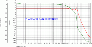 THORSTEN CL GP.gif24.3 KB · Views: 137
 -
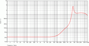 THORSTEN OUTPUT Z.gif27.3 KB · Views: 144
 -
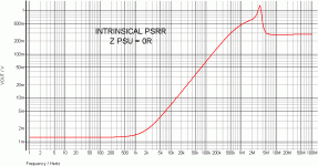 THORSTEN PSRR.gif28.9 KB · Views: 144
 -
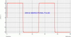 THORSTEN SR1.gif21 KB · Views: 147
 -
 THORSTEN SR2.gif19.7 KB · Views: 134
 -
 THORSTEN SR3.gif16.6 KB · Views: 58
 -
 THORSTEN THD1-graph.gif38.8 KB · Views: 66
 -
 THORSTEN THD10-graph.gif38.6 KB · Views: 67
 -
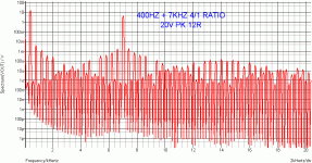 THORSTEN IMD 047.gif38.8 KB · Views: 67
 -
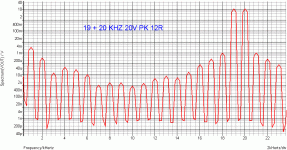 THORSTEN IMD1920.gif32.5 KB · Views: 59
Hi,
The schematic ACTUALLY is quite simple. There are some aparent complications from certain design techniques.
As I noted, compensation has not been fully worked out and may need changes. Also the feedback circuit is not completely fixed. Depeding on results I may completely remove NFB or increase it.
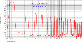
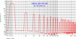
I am not sure precisely what you are simulating and what Iq 152mA X 2 is meant to mean?
Each Output BJT requires nominal 120mA Iq, the precise amount will depend on testing the completed design. It also seems the compensation may need a few lead compensation Cap's and maybe a few pF miller, this will have to be worked out.
Also, I have realised later that one capacitor better had one connection shifted. The one bridging the 56K resistor in the input current mirrors collector needs to be shifted to connect the two gates of the J-Fet VAS buffer... Not sure it will make a difference in the simulator though.
Ciao T
I find this schematic quite complexe but i suppose that i m inclined toward simplicity , albeit not simplisticisms...
The schematic ACTUALLY is quite simple. There are some aparent complications from certain design techniques.
As presented it need some reworks to be a practical and reproducible design.
As I noted, compensation has not been fully worked out and may need changes. Also the feedback circuit is not completely fixed. Depeding on results I may completely remove NFB or increase it.
I am not sure precisely what you are simulating and what Iq 152mA X 2 is meant to mean?
Each Output BJT requires nominal 120mA Iq, the precise amount will depend on testing the completed design. It also seems the compensation may need a few lead compensation Cap's and maybe a few pF miller, this will have to be worked out.
Also, I have realised later that one capacitor better had one connection shifted. The one bridging the 56K resistor in the input current mirrors collector needs to be shifted to connect the two gates of the J-Fet VAS buffer... Not sure it will make a difference in the simulator though.
Ciao T
On the subject of simple vs complicated, I'd say that's a VERY relative, as Thorsten beat me to the punch.
As I see it, there are two basic layers to every device - the essential audio circuitry and the auxilliary circuitry.
For example, overvoltage/overcurrent protection circuitry in my case will add 18 components, which are, under normal operating conditions, 100% wasted, as they actually do nothing. You can remove them and nothing will happen. They are there "just in case" some dummy short circuits the outputs, or has a brilliant idea of connecting two sets of 4 Ohm speakers which go way below 4 Ohms and then tries for full power.
As I see it, they are still a must - just in case. Their cost in comparison with possible damage is totally insignificant, but I have seen many burnt out amps with their "protection" fuses intact. Nothing is as fast as a transistor.
Or the DC servo circuit. It also adds 14-16 components, but has a crucial role to play - in comparison with AC coupled units, one with a DC servo will look more complex, given that it can be replaced by just two capacitors. However, when you factor in the additional circuitry needed to null the DC offset, things begin to change, as at least three, and typically more like 6 or 7 additional components get into the picture.
Lastly, there's the DC and thermal protection circuits. For reasons of sheer lunacy, much of the DIY community feels they somehow impair sound quality and choose to leave them out. I see this as a downright stupid move, that's sticking your head in the sand and hoping for the best. Some choose to show it, some set it aparat; I show it because my concept is that of a power amp module, i.e. everything right there, so you can parallel amps to whatever number takes your fancy. But that's my choice, it has its pros and cons, just like every other choice.
The point is, if one is careful and chooses to have it all, the resulting schematic will appear to be very complex, because all these auxilliary circuits will add around 50% more parts over the actual audio circuits.
If you feel that say 4 22uF caps are better than one 100uF cap, before you know it, your schematic starts becoming complex.
I would rate Thorsten's schematic, bearing in mind it's just a preliminary one (with much of, as he put it "housekeeping", NOT included), as complex as it needs to be for the required results. About middle of the road.
If anything, I'd ask him to add another pair of output transistors, not because he really REALLY needs it, but again, to be on the safe side. Those devices lose 1.43 Watts of power per every degree centigrade over 25 deg, ambient, meaning that if somebody start to misuse it, it will get hot rather fast and its effective power dissipation will be reduced quite significantly, to less that 100 W per device - that's assuming he has mighty heat sinks, and he's going to need them if he takes up his upper limit of biasing. Anyway, his amp is his business, but I sure would include a fourth pair, and I use mighty heatsinks (probably the same as Thorsten's, mine are Fisher of Germany too).
If you think I am simplifying things, just let me know and I'll post some REALLY complex schematics of otherwise well known and well regarded products, which I guarantee will change your concept of the word "complex".
Last edited:
Hi,
The schematic ACTUALLY is quite simple. There are some aparent complications from certain design techniques.
As I noted, compensation has not been fully worked out and may need changes. Also the feedback circuit is not completely fixed. Depeding on results I may completely remove NFB or increase it.
I am not sure precisely what you are simulating and what Iq 152mA X 2 is meant to mean?
Each Output BJT requires nominal 120mA Iq, the precise amount will depend on testing the completed design. It also seems the compensation may need a few lead compensation Cap's and maybe a few pF miller, this will have to be worked out.
Also, I have realised later that one capacitor better had one connection shifted. The one bridging the 56K resistor in the input current mirrors collector needs to be shifted to connect the two gates of the J-Fet VAS buffer... Not sure it will make a difference in the simulator though.
Ciao T
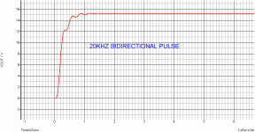
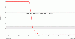
Unfortunately , my free simulator has limited nodes number
so i simulated with two pairs of output devices , each pair
being biaised at 152mA for a total of 304mA quiescent current.
The load is increased to 12R to compensate a little for
the absent third pair , albeit at those high bias currents it makes
little difference in respect of the relatively low simulated output level.
A classical dominant pole compensation works better in this amp ,
about 22pF from the VAS collectors to their fets drivers gates,
while at the same time increasing the two 100K local loop FB resistors
to at least 1M.
Phase response will be correct , IMD 400/7K is significantly lower
wich is important since this measure is way more significant than
the overkill 19+20K tests.
The use of a full fet cascode is useless , the upper pair can be replaced
by bjts with no change in the perfs.
Also , the fet differential input pair must have no more than 8/12V Vgd
as generaly the drain/gate leaking current rise very sharply above those values.
Last edited:
Hi,
Ahh, okay, now it makes sense. Maybe even drop another pair and use 16R, if it helps to preserve the rest.
Not going to happen. This creates the usual amp with the usual results. Not interested.
I see around 0.05% IMD for 25W/8R equaivalent, or -8dB. I am not very perturbed. I know you want to see -90dB, but that is your goal, not mine.
As the circuit uses essentially a Hawkesford cascode with a bootstrapped CCS feeding is, this is indeed so. However someone already put the Fet's there, so I'll keep them. ;-)
For anyone building from scratch BJT's are indeed fine.
I don't have the curves for the 2SK246, however lowered drain current reduces the gate leakage.
Here the input Fet's are running at maybe 0.2mA (which means we will have around 2.2V reverse bias on the input diodes, which has it's own rewards) and I'm estimating maybe 5nA at the set 25V appx., so nothing to loose sleep.
Also, if your Sim program is free, would you mind sharing the Schematic/Models and a download link, so others can play too. This schematic could be a good exercise to illustrate the trade-offs in amplifier design, different compensation schemes, feedback schemes and levels and so on.
One could see how much difference cascoding the VAS makes for example. Who knows, we may even find two completely separate versions that offer different tradeoffs. I make my optimisations and you do yours.
Ciao T
Unfortunately , my free simulator has limited nodes number so i simulated with two pairs of output devices , each pair
being biaised at 152mA for a total of 304mA quiescent current. The load is increased to 12R to compensate a little for the absent third pair , albeit at those high bias currents it makes little difference in respect of the relatively low simulated output level.
Ahh, okay, now it makes sense. Maybe even drop another pair and use 16R, if it helps to preserve the rest.
A classical dominant pole compensation works better in this amp , about 22pF from the VAS collectors to their fets drivers gates,
while at the same time increasing the two 100K local loop FB resistors
to at least 1M.
Not going to happen. This creates the usual amp with the usual results. Not interested.
Phase response will be correct , IMD 400/7K is significantly lower wich is important since this measure is way more significant than the overkill 19+20K tests.
I see around 0.05% IMD for 25W/8R equaivalent, or -8dB. I am not very perturbed. I know you want to see -90dB, but that is your goal, not mine.
The use of a full fet cascode is useless , the upper pair can be replaced by bjts with no change in the perfs.
As the circuit uses essentially a Hawkesford cascode with a bootstrapped CCS feeding is, this is indeed so. However someone already put the Fet's there, so I'll keep them. ;-)
For anyone building from scratch BJT's are indeed fine.
Also , the fet differential input pair must have no more than 8/12V Vgd as generaly the drain/gate leaking current rise very sharply above those values.
I don't have the curves for the 2SK246, however lowered drain current reduces the gate leakage.
Here the input Fet's are running at maybe 0.2mA (which means we will have around 2.2V reverse bias on the input diodes, which has it's own rewards) and I'm estimating maybe 5nA at the set 25V appx., so nothing to loose sleep.
Also, if your Sim program is free, would you mind sharing the Schematic/Models and a download link, so others can play too. This schematic could be a good exercise to illustrate the trade-offs in amplifier design, different compensation schemes, feedback schemes and levels and so on.
One could see how much difference cascoding the VAS makes for example. Who knows, we may even find two completely separate versions that offer different tradeoffs. I make my optimisations and you do yours.
Ciao T
If you don´t like the term "DF" feel free to invent your own. But DF _is_ a well defined number and the impact on bass response can be calculated,...
My original point was that THD, (T)IMD, DF and co are advertising numbers, not technical engineering specifications.
...
simulated, measured and is audible. What else do you want ?
- Status
- Not open for further replies.
- Home
- Member Areas
- The Lounge
- Sound Quality Vs. Measurements
