A Parasound Z3 is NOT related to me, or to hi end audio in any way. Of course, for a bedroom or office system, it might be OK. It is consumer mid fi.
Understood. It will suit what I need on my test bench perfectly as it is the same footprint as my acquisition unit and interface box, has better output stupid-proofing and decent bandwidth, DF and appropriate power for testing. It gives me a lot of space back on the table. So, about right for that use.
The price range is for sure mid-fi, I just hope well executed. At under 400 new, it is below the range where designers have many options.
I suggest it a fair comparison as all of the amps I mention are available for under $200 used. So, for money a civil servant can afford, how well can one do? These are all low power and not intended for full range above background listening. But, that is in the range of what bothers my wife with horns and some violins. So, a modern consumer amp that is well reviewed vs. some older ones and reuse on the bench. win-win.
In spite of some news reports, our wages have been frozen for several years, withholdings are going up faster than the price of gas, and for my job, I am about 50% less than the private sector wage, so a 2125 or A23 is not in the near future and way too big anyway. I need all my spare change for much better drivers so I can move from mid-fi speakers. Studio 20's were a bargain for their quality in their price point, but they are not in the serious range. My own speakers have not quite bested them yet but I am getting close.
If you are 'broke' then DIY or leave it alone. With the added mark-ups that are necessary with successful companies, AND actually paying people to build and test amps. What looks like a great deal, MUST be compromised from what you can make on your own, here.
Last edited:
The flip side of that is the huge mark up required on low quantity parts. A cap that may run $23 each at Mouser is about 6 bucks per thousand. There are no surplus stores left around here. Mouser, Digi-Key, Newark is it. A handful of resistors, two tubes, caps, and hardware to put a long tail splitter in a cheap Chinese 6P1 cost as much as the amp did. DIY electronics, if not just POOGE level, is really expensive. Just the Centari paint for my last speakers was over $200. A spool of 14 gauge enameled wire cost more than pre-wound coils from Parts Express. No, DIY is not cheap. I am quite aware of production costs as I was a manufacturing quality engineer in my past life. We DIY because we build things we can't buy and because it is our hobby. There are things we can't DIY easily, like more than two layers on a board or plated through holes. I am just learning how to deal with SMT.
For those not in manufacturing, looking at a $1200 amp is not that impressive. Looking at a $35million Cray is not impressive. Look at a $5 calculator. Impossible. Blows my mind. At least the amp will have a longer life than either the calculator or Cray computer.
For those not in manufacturing, looking at a $1200 amp is not that impressive. Looking at a $35million Cray is not impressive. Look at a $5 calculator. Impossible. Blows my mind. At least the amp will have a longer life than either the calculator or Cray computer.
Bearing in mind I'm not sucking anything out of thin air; that info's on the datasheets, besides which Thorsten's pointed out that the temperature fluctuations are easily observed with the right equipment.The time constants being mentioned (e.g., by godfrey) ...
Maybe so, but only a very small amount. E.g. the 10 degree temperature fluctuation mentioned earlier would only cause about 20mV variation of Vbe in a typical EF output stage, so probably less than 0.1% distortion open loop....would cause distortion well above the LF cutoff of most amps.
It won't be noticeable on a THD+noise vs frequency plot if it's swamped by distortion from other sources, or if the distortion is pushed below the noise floor e.g. with global feedback.
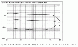
The best place to look for signs of thermal distortion would seem to be in an amp with very good open-loop linearity and not too much (if any) feedback. Charles Hansen springs to mind as someone who likes to do things that way. After much scratching around on the Stereophile website, I found measurements of his MX-R amp here. Sure enough, there's a rise in distortion below about 100Hz. Not much, but it's there.
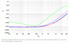
I found a couple of other examples too. The Musical fidelity AMS100 (reviewed here) has very low distortion, but when pushed hard into 2 ohms the distortion rises above the noise floor and is seen to be increasing at low frequencies.
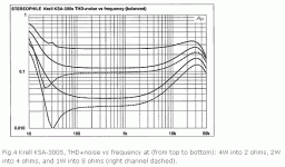
Perhaps the most interesting is the Krell KSA-300S (reviewed here). The Krell's thermal distortion is as bad as the chipamp example given by Doug Self here. How Krell got that right (or should I say wrong?) is a mystery to me.
Attachments
Last edited:
It is amusing that as you say the most visible examples of thermal distortion will be from "no global feedback" amp circuits – or monolithic/hybrid circuits with input and pwr components closely thermally coupled
While it seems to be the “nfb” proponents that are throwing up “thermal modulation” as an error of “those bad high feedback amps”
In fact in global negative feedback amps it is easy to have high audio frequency loop gain, low TC feedback R, and diff pair well separated from output stage power dissipation swings
high gain, bootstrapped cascode can keep input diff pair pwr delta order of uW for all linear operating range signals
then global feedback easily suppresses the output impedance modulation, distortion from thermal gain shifts in VAS, drivers, output stage - just like it controls the same part's variation's of 2-10x gm, ft swings over the normal drive of output stage into a load over the full cycle of Class AB operation
some here seem to have a distinct anti global feedback agenda and won't give it credit for its real strengths - one of which is practically eliminating thermal feedback by separating the differencing circuit from the pwr parts either in discrete construction or using composite amp with thermally separated input op amp wrapping global feedback around the output monolithic chip amp or hybrid buffer
Last edited:
Sy,
D. Self shows a complete amplifier, with large amounts of feedback and degenerated emitter followers. I remarked before that using these can swamp out the measurable effects, but you must have missed that.
However, what D. Self has not proven and what you claim is that the signal does not change the temperature of the actual chip in the transistor (as opposed to the signal envelope), which would require determination using any number of direct methods (like sensing VBE and subtrating signal related changes, directly observing the temperature of the die junction using suitable equipment etc.).
And while you suggest such experiments, it is evident that you did not carry out such experiments.
If you wish to adjust your contention to:
If amplifiers are designed and constructed and biased according D. Self's recommendations (this includes some interesting details on physical construction) then no evidence of thermal distortion is observable in the THD Plots, indicating that Thermal distortion is below that of rest of the amplifier's distortion mechanisms or that Thermal distortion applies at much higher frequencies than assumed by D. Self and repeated by you and becomes part of the overall picture of distortion and cannot be reliably separated out.
Then I have no beef.
As long as you insist that there is no observable temperature change, which you so far have, and you do not provide experimental proof, which you have not, I cannot accept your contention as being proven or even as being reasonable and likely to apply.
As contrary to your claims an appreciable body of work exists that illustrates otherwise, I can only consider your claim as being and being maintained in direct opposition to observed and documented scientific fact.
Ciao T
Actually, there's quite a bit of data in that series of papers which clearly show the absence of the predicted rise in LF distortion. Unless the "Audio Precision" logo is some sort of spice simulator with which I'm unfamiliar.
D. Self shows a complete amplifier, with large amounts of feedback and degenerated emitter followers. I remarked before that using these can swamp out the measurable effects, but you must have missed that.
However, what D. Self has not proven and what you claim is that the signal does not change the temperature of the actual chip in the transistor (as opposed to the signal envelope), which would require determination using any number of direct methods (like sensing VBE and subtrating signal related changes, directly observing the temperature of the die junction using suitable equipment etc.).
And while you suggest such experiments, it is evident that you did not carry out such experiments.
If you wish to adjust your contention to:
If amplifiers are designed and constructed and biased according D. Self's recommendations (this includes some interesting details on physical construction) then no evidence of thermal distortion is observable in the THD Plots, indicating that Thermal distortion is below that of rest of the amplifier's distortion mechanisms or that Thermal distortion applies at much higher frequencies than assumed by D. Self and repeated by you and becomes part of the overall picture of distortion and cannot be reliably separated out.
Then I have no beef.
As long as you insist that there is no observable temperature change, which you so far have, and you do not provide experimental proof, which you have not, I cannot accept your contention as being proven or even as being reasonable and likely to apply.
As contrary to your claims an appreciable body of work exists that illustrates otherwise, I can only consider your claim as being and being maintained in direct opposition to observed and documented scientific fact.
Ciao T
Hi,
Forgive my ignorance, but please explain how does "global feedback practically eliminating thermal feedback by separating the differencing circuit from the pwr parts" actually work physically?
???
And what particular magic creates said feedback in circuits that avoid global feedback while having different parts of the circuit separated thermally or in fact are free from thermal effects but lack global looped feedback?
Ciao T
some here seem to have a distinct anti global feedback agenda and won't give it credit for its real strengths - one of which is practically eliminating thermal feedback by separating the differencing circuit from the pwr parts
Forgive my ignorance, but please explain how does "global feedback practically eliminating thermal feedback by separating the differencing circuit from the pwr parts" actually work physically?
???
And what particular magic creates said feedback in circuits that avoid global feedback while having different parts of the circuit separated thermally or in fact are free from thermal effects but lack global looped feedback?
Ciao T
In idealistic theory, global feedback is predicted to remove thermal deviations, amplitude deviations, etc, etc. However, real circuits are not perfect in their input linearity, and so global feedback can make as much trouble as it is predicted to fix.
Barrie Gilbert proved this very well, but Otala predicted, and measured it first.
Barrie Gilbert proved this very well, but Otala predicted, and measured it first.
Have to admit, I drop off everything we have not used in a year or so to Salvation Army, but I have not browsed the store. I need a toaster oven to solder smt. I never thought about them for electronics. The pawn shops here only sell gold and guns. Everything else is priced to sit on the shelf so it does not look like just a gun dealer. One had a Jolita on the shelf. He wanted more than a new one. When asked, he admitted most of what was on display had been there for years as a prop. I wonder if Goodwill is where the gentleman got his foil hat I saw last time I was out at LBL. Kept the CIA from beaming thoughts into his head I think.
Tvr, it is really the situation that a very quiet input stage, at least until recently, is fairly easily overdriven, AND the harder the feedback loop tries to make the output 'perfect' the more tendency to 'stress' the input stage and generate a 'deviation' that might not even be detectable in most audio tests, such as harmonic or even 2 tone IM distortion. Some call this FM distortion, others have called it PIM. In any case, most of the usual audio ready test equipment does not measure this.
To make least easily overdriven input stages, either jfets, with or without significant resistive degeneration (more noise) are used, or just significantly more resistive degeneration is added to a bipolar pair (significantly more noise, compared to without resistor degeneration).
Complementary differential jfet input stages can be very linear in this regard, reasonably quiet too! I work down to 0.4nV/rt Hz or better, in my best designs.
So I understand, if you restrict the feedback to within each stage, you also don't have to deal with the phase/propagation delay of global feedback that was the source of some distortions in early SS amps?
Propagation delay is essentially zero for any practical amplifier; it exists mostly as audiophile mythology. Feedback stability has to do with number and placement of rolloffs, not number of stages (except insofar as that affects number and placement of rolloffs).
Hmmm. Please bear with me here as I could be quite misinformed. I am trying to think back on papers talking about TIM and SID from years ago.
Slew magically is not relevant to audio? Or is this that a decent transistors have such a high slew rate that is is not an issue that matters? 99% on my bench experience was digital, so I may be carrying baggage. Yet, I see caps in the feedback circuit, parastatic L and C. That must get something out of kilter. The idea I remembered was by putting feedback within each stage it reduced the accumulation of effects. This could easily be "Madison Ave. Engineering", that is why I ask.
Slew magically is not relevant to audio? Or is this that a decent transistors have such a high slew rate that is is not an issue that matters? 99% on my bench experience was digital, so I may be carrying baggage. Yet, I see caps in the feedback circuit, parastatic L and C. That must get something out of kilter. The idea I remembered was by putting feedback within each stage it reduced the accumulation of effects. This could easily be "Madison Ave. Engineering", that is why I ask.
Slew magically is not relevant to audio?
It is, but it s no more a problem for quite some time.
Attachments
Within reason, slew rate matters. But that's 1968-era engineering, and I can't remember the last amp I saw with slewing distortion (no-one uses 741s in high voltage audio circuits). Slew in audio amps has nothing to do with propagation delay (that's on the order of nanoseconds).
The relevant parameters in amp stability are rolloffs- number and position. The basic control theory that allows factories to operate, planes to fly-by-wire, and NASA to drop spaceships to within meters at distances of tens of millions of miles works fine for the hifi in your living room. The caps in feedback networks and those which set dominant poles are there for stability and to allow minimization of distortion. And there are lots of designer tricks to put in clever little zeros.
Bob Cordell's excellent book gives a nice introduction to feedback theory applied to audio amps. I'd highly recommend it.
- Status
- Not open for further replies.
- Home
- Member Areas
- The Lounge
- Sound Quality Vs. Measurements


