All good stuff... nice contribution to current (?) apps.... the smps is coming on fast and what new problems would be comparable to the analog approach? No transformer issues but still rctifier and filter and rfi/emi, leak-thru freqs. I mean - after doing this type power supply, the other type(s) would also be great for everyone to appreciate the issues involved when applying various power supply technologies to amplifiers and music reproduction.
-RNM
-RNM
Last edited:
All good stuff... nice contribution to current (?) apps.... the smps is coming on fast and what new problems would be comparable to the analog approach? No transformer issues but still rctifier and filter and rfi/emi, leak-thru freqs. I mean - after doing this type power supply, the other type(s) would also be great for everyone to appreciate the issues involved when applying various power supply technologies to amplifiers and music reproduction.
-RNM
I spent some of today looking at a problem. The venue has around a hundred switching power supplies loading a single three phase breaker box.
Some of the switchers are 300 watts others are as small as 60 watts.
The circuit breakers have failed.
The question was if the harmonics of the power supplies did it.
After looking at the actual measured AC harmonics and radiated distortion, my suspicion is the breakers were installed incorrectly.
The harmonics from the switching power supply are lower than much of what I have been seeing from linear power supplies!!!!
If I get a chance I will post the spectrum of the switching power supply currents.
Were the breakers approved for use in the specific panel.I spent some of today looking at a problem. The venue has around a hundred switching power supplies loading a single three phase breaker box.
Some of the switchers are 300 watts others are as small as 60 watts.
The circuit breakers have failed.
The question was if the harmonics of the power supplies did it.
After looking at the actual measured AC harmonics and radiated distortion, my suspicion is the breakers were installed incorrectly.
jn
Were the breakers approved for use in the specific panel.
jn
Yes. New construction of large venues gets special pricing direct from the manufacturers. My main breaker here is several hundred dollars through normal distribution. A spare picked up from a friendly contractor during a large project was $80.00.
These are fancy breakers that monitor the current and combine into an energy management system. So either they set the trip point switch incorrectly or didn't mount them in the panel correctly.
Balancing the phases "fixed" the problem and no one wants to send me a failed breaker, so I suspect installation was the actual issue.

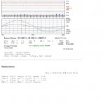
This is the data on the switcher. 8.6% line distortion at 230V in. Look at the current vs voltage graph. Linear supplies are nowhere near that good. The spectrum is hard to read as it is a bar graph but you can see it is higher order stuff.
There are also pages of radiated RFI in uV.
There are also pages of radiated RFI in uV.
Attachments
This is the data on the switcher. 8.6% line distortion at 230V in. Look at the current vs voltage graph. Linear supplies are nowhere near that good. The spectrum is hard to read as it is a bar graph but you can see it is higher order stuff.
There are also pages of radiated RFI in uV.
Clearly that one has pretty good power factor correction.
It's often supposed that traditional iron/copper mains frequency "linear" supplies have no RFI. But without proper snubbing of reverse recovery spiking in the power diodes, they can be quite noisy. At least the noise is synchronized.
Just want to note that Toshiba still makes low noise FETs (only n-channel and smd though): 2SK880, 2SK208, 2SK209. And they are cheap...
Thanks for that, Georg. I only use N channel and ain't skeered of surface mount.

se
About the advantages of SMPS two remarks.
First look at where the market turns for sensitive applications. I understand AP switched to switch mode because no linear PS could deliver the same clean power. Linn uses it. The reason is because it provides benefits.
As seen from the technology itself, what I mean with the added layer of intelligence is that a first stage of recitification, followed by a oscillator circuit that creates AC of precisely defined properties, followed by an optimized transformer operating at high frequency, removes much of the low end hash you never seem to get completely rid of with linear power supplies. Filtering out the high frequency components from the rectified output is obviously much easier than filtering out 50 or 60 Hz and low frequency harmonics from a linear supply.
And I am not even talking about the benefit of having a regulated PS.
Last edited:
add:
Smaller magnetics, can even use PCB based planar transformer, which is easier to screen, and easier to screen against capacitive coupling in the transformer.
Smaller footprint for a given power rating, smaller loop area. Better thermal management.
Smaller capacitors (no electrolytics in some cases).
Noise way above the audio spectrum.
Surface mount devices are far superior for heat dissipation...metal can transistors (dissipation)
Surface mount devices are far superior for heat dissipation...
Dual output stage on an Al2O3 board, face to face with the 'heatsink' panel.
Attachments
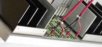
Jacco, marce is likely talking about devices that expose the die/substrate to a pad on the underside, rather than the pretty high impedance of the epoxy body, when trying to pull the heat through the top, like you have there.
using these devices means 2 thermal interfaces are cut out of the thermal impedance calculation.
even something as simple as the LME49726 opamp in a MSOP8 powerpad package, allows a small opamp that will put out 300mA at 5v output. I havent even picked the highest, just one i'm looking at today.
yep, the audio cliches for numbers of things nolonger hold true, but that wont stop many people hanging on to them until they have no options left.
Last edited:
These are fancy breakers that monitor the current and combine into an energy management system. So either they set the trip point switch incorrectly or didn't mount them in the panel correctly.
Balancing the phases "fixed" the problem and no one wants to send me a failed breaker, so I suspect installation was the actual issue.
Was the panel fed delta or wye? Excessive neutral pull could cause overvoltages. Given the waveform shown with the dead just in front of zero crossing, I'd first look at the neutral currents.
Reminds me of Zsa Zsa trying to add single digit numbers so she doesn't blow the generator out.
Jacco, marce is likely talking about devices that expose the die/substrate to a pad on the underside, rather than the pretty high impedance of the epoxy body, when trying to pull the heat through the top, like you have there.
Smt packages will generally have one or more of the leadframe coppers being used to remove heat from the die. That is done by bonding the die backside directly on the copper, heat transports through metal to the external solder pads of the board. Any lead which is not chip backside will have a very tiny wire bonded chip to pad, they are not direct heat transport mechanisms, there will be a little due to side conduction of the encapsulation epoxy.
It's the exact same with the big 247 and TO-3 cases. The chip is bonded to the metal, and heat exits that way.
I do like that Al2O3 board, it's a great heat spreader.
jn
Last edited:
that depends what you are talking about, i'm working with some passivated GaN Die parts that have a pretty much direct connection, just a solder bump in the way. nothing wrong with the pic above, as you mention its pretty neat indeed, but heatsinking from the top of the package is always quite a bit worse than a metal on metal connection. same with the bottom as long as its the epoxy rather than soldered, still rather neat, but i'm pretty sure its not what marce had in mind.
edit:actually reading my wording in the above post you are correct, my mistake. I didnt mean to say die for the msop, rather the leadframe.
edit:actually reading my wording in the above post you are correct, my mistake. I didnt mean to say die for the msop, rather the leadframe.
Last edited:
like you have there.
The SMT's have their large collector lead soldered to pads at the underside.
Contact surface of an SOT-223 larger lead is 0.01 in2 , each pad is part of a 0.1 in2 area of the output lane.
Each half of the board image manages 20A peak in 1 Ohm, aka ~2.2A per output device.
Hence the 9 Allen bolts to clamp the board to the front panel.
(each of the SOT-223 can do 15A peak, from a 1/30 in2 size body, btw)
Last edited:
aah sorry Jacco, I misunderstood the photo, I took the exposed board as being the same as the other 2 ie. lots of tiny sot232, but without the heatsink to illustrate what was underneath.
looking at it again now thats stupid, the connections would foul on the heatsink :redface:
looking at it again now thats stupid, the connections would foul on the heatsink :redface:
Last edited:
- Status
- Not open for further replies.
- Home
- Member Areas
- The Lounge
- John Curl's Blowtorch preamplifier part II