That was a brilliantly simplified but powerful remote ("Froxwand" iirc?). A lot of good ideas, too expensive, and ahead of their time.Wow, there's a name from the past! I designed their controller (the hand-held one). I was not surprised to see them go belly up and sink.
The remnants of Frox morphed into Mike Watts' and Kathy Lee's Harman Interactive Group, which got Harman into the multimedia speaker biz and greatly facilitated a large improvement in my own financial condition.
Re the switchers, I just cannot conceive that a switcher and a MM/MC equalizer make a good marriage - even if the switcher is a wall wart type. People agonize over resistor types (even sound differences between brands), low noise JFET's etc and then power their masterpieces up with an SMPS?
Kind of like this wireless charging thing going on now. Big customers are demanding 10mW standby power on mobile phone chargers and efficiency >>80% (remember, we are talking about 5W chargers here), and then there is a another group of individuals pushing wireless charging that barely makes 70% efficiency - and has half a pound of copper in the coupling coil. Confusing

Kind of like this wireless charging thing going on now. Big customers are demanding 10mW standby power on mobile phone chargers and efficiency >>80% (remember, we are talking about 5W chargers here), and then there is a another group of individuals pushing wireless charging that barely makes 70% efficiency - and has half a pound of copper in the coupling coil. Confusing
As the circuit under power can vary in power draw, the supply current rating should be 20% greater than the draw at a decent minimum. In a power amplifier the maximum power is required infrequently except for Class A amplifiers.
You might want to test the assumption. Though not a steady state condition, the infrequent peaks are pretty frequent IMO. About how infrequent and how damaging Power amp curent draw... average and peak levels... the peak levels matter most regarding the generation of the most noise/unwanted freqs. of course, what power rating, what load and what transformer for them. In other words, you dont want to get near the levels demanded from the amp/load by the transformer and you cant always assume the VA ratings shown will best apply to your situation. "Trust but verify" as some old geezer was fond of saying.
Thx-RNMarsh
Last edited:
Switching power supplies are about the only practical answere for mfr'ers... multiple input volts/freqs and high efficiency and small size and low weight, cost etc etc... not to mention, as was said, PFC or power factor correction. They have a lot of advantages.... but emi/rfi-free isnt one of them...without careful design. So extra effort/cost for audiophile use would deal with that.
Would be nice to see a new forum on their designs for high-end audio apps. But for DIY at this time they arent as easy to make and excellent designs on a budget and be reliable are not off the shelf with our special/nitch needs and desires. Or are there some?
Thx-RNMarsh
Would be nice to see a new forum on their designs for high-end audio apps. But for DIY at this time they arent as easy to make and excellent designs on a budget and be reliable are not off the shelf with our special/nitch needs and desires. Or are there some?
Thx-RNMarsh
Last edited:
That was a brilliantly simplified but powerful remote ("Froxwand" iirc?). A lot of good ideas, too expensive, and ahead of their time.
I can't remember their name for it, but many of the ideas (like the pressure buttons) ended up being used in the X-Box controllers years later. A very smart fellow from Apple, Bill Louis, adapted my pressure sensor array to make the first version of the now-iconic circular control found on every iPod.
They look really interesting, and better made than many of the China sourced ones I have dealt with in the last few years. The pricing is higher (you get what you pay for) but not unreasonable. It also shows that the price of admission to SMPS is fairly constant until you go over a threshold and then it goes up a lot. Its the cost of boards, transformer and fets, which don't change a lot with power.
I wonder how well one of these in an aluminium box would work? The aluminium would probably provide enough shielding for EMI and heat sinking. The input filter should be different (medical grade) to prevent noise currents from getting into the system grounds.
Bonsai, there is no consistent reason for making a commercial audio design. Some people want a 'gimmick' like batteries, or even switching power supplies. Others just want to save heat, space, and money.
In my opinion, really good audio quality is easier to make with conventional, but quality AC power supplies. It is just quieter.
In my opinion, really good audio quality is easier to make with conventional, but quality AC power supplies. It is just quieter.
Where I am now, Northern Belgium, as well as my preciois place in South NL, it was always above 230 when I checked.
jan
I have 230V spot on here in Vienna (Austria). (Was 220V years ago).
You might want to test the assumption. Though not a steady state condition, the infrequent peaks are pretty frequent IMO. About how infrequent and how damaging Power amp curent draw... average and peak levels... the peak levels matter most regarding the generation of the most noise/unwanted freqs. of course, what power rating, what load and what transformer for them. In other words, you dont want to get near the levels demanded from the amp/load by the transformer and you cant always assume the VA ratings shown will best apply to your situation. "Trust but verify" as some old geezer was fond of saying.
Thx-RNMarsh
One of the Duh moments I had was when I realized that with digital recordings one could actually size things correctly so you never clipped!
Now there are folks who want clipping as part of their music. Some dance systems actually are used at 50% clipping. (They blow up a lot of power amplifiers.)
In a bus station during use the old goal was for 10db of headroom, which is 1-10% clipping on normal speech.
These days 20 db is more typical which gets clipping under 1%. The exception being stadiums where at full volume 10 db is even tough to get. But when the crowd is screaming quality isn't much of an issue.
In doing symphony orchestra amplification I find 30 db of headroom is adequate to avoid hearing clipping.
Now there certainly are underpowered stereo consumer music systems, particularly video related multichannel stuff.
But my 20% overrating was more in line with well known reasonably constant loads to allow for component tolerance variations. Using 5% parts with normal tolerance distribution would allow for 16 value critical parts before you might get out by 20%.
Talk about one extreme (batteries) to another.
After which the outputs of both smps blocks are filtered several times the oldfashioned hardware way : 72.600uF total.
Me sorta grew up with this beauty, she went to bed when I left for university.
(3-cilinder submarine, L+R battery of 168 cells of 2.1V, instead of Forward + Back battery)
All-DC, with 350V-1500A through a 400mm2 cable (subs require far less power submerged), only Biot-hazard law complaints.
Thyristor noise and SMPS hash would have been some fun.
Silence is Golden.
Attachments
The constant voltage transformer (Sola) work by running the transformer at saturation. They have a harmonic neutralization (big cap) to remove the excessive harmonics but are usually running around 3-5% THD at least. They all buzz. Its magnetostriction and really no amount of potting can remove it. The steel itself is expanding and contracting and has a lot of force behind it. Transformer acoustic noise is a bigger real headache than the radiated fields and much harder to get rid of. Usually if you can't hear it your listening room is too noisy for quality listening. Its rarely inaudible. Export to Japan if you want a crash course in this.
The resonant cap is usually tuned to increase the 3rd harmonic. they are usually run at 1.9 and 2.1 so quite heavily into saturation, I was tasked with working on small ones usually potted in a wound strip steel enclosure, with extra blank lamination strips stuffed in before the potting compound was added to keep the external field down.
The best case minimum power was about 30% of max, more usually run between 60% and 100%, and usually designed for +-10% mains, ocasionally more.
at the place I worked at the largest was 750 watt, smallest about 60 watt.
for best result you need skinny laminations, but that means more offcut from a strip sheet run through the E/I cutter.
That is also for Pano
The large amount of 3rd gives an easy long conduction angle for the diodes though...
Well I ran a bit more than 100 measurements today on power transformers. Attached is one of them.
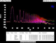
This shows the harmonic distortion of a flatpack style transformer with dual bobbins. A primary and secondary on each bobbin. It is measure both with and without a 25 ohm load across series connected secondaries. Since each should be 12 volts that gives just about a 1 amp draw. Input voltage is 120 or 120 x 1.1 (130 ish) at 50 hz.
My conclusion is that it should be loaded with a 10 uf capacitor across the secondary in most uses.
Note the distortion does increase with higher voltage, but not as much as from lower frequency when compared to the 60 hz curves.
I'll show more later if anyone is interested.
Attachments
Last edited:
Simon,
Where you are in PA the power is sourced at 50hz? I have been under the assumption that all US power was a 60hz source.
Actually until recently there were some areas with 25 hz power! DC was used in parts of New York City until a few years ago.
But I am using the signal source in the AP analyzer and an Ashly PE3800 amplifier in the bridged mode.
I also ran curves at 60 hz. I will do some frequency response curves later.
Actually until recently there were some areas with 25 hz power! DC was used in parts of New York City until a few years ago
Except that was only for some selected "ancient" equipment like those elevators that had a concierge to operate them. Many subways are still DC and 16 2/3 Hz is still used in Europe for trains. Long haul power transmission has also revisited DC.
Nov 14 2007 New York Times had the article about Con Ed dropping DC service and how they went to converters! I don't know how to past the web info on this phone, but you should be able to find it.
BTY many elevators still use DC. AC motors try to start up and lock on frequency-speed so they require complex controls. DC is current to torque and naturally provides smooth motion.
BTY many elevators still use DC. AC motors try to start up and lock on frequency-speed so they require complex controls. DC is current to torque and naturally provides smooth motion.
Nov 14 2007 New York Times had the article about Con Ed dropping DC service and how they went to converters! I don't know how to past the web info on this phone, but you should be able to find it.
Yes the point is there were not DC powered wall outlets (with warning signs "Don't plug ANYTHING into this"). Con Ed subsidized in some cases the converters to operate legacy equipment.
My conclusion is that it should be loaded with a 10 uf capacitor across the secondary in most uses.
Interesting work. Will this be an article on Linear Audio or something?
When you get round to it, you could investigate the effects of a "swenson snubber" as well.
Different type of snubber - John Swenson - Tube DIY Asylum
- Status
- Not open for further replies.
- Home
- Member Areas
- The Lounge
- John Curl's Blowtorch preamplifier part II