I do like the way AP does the transformer feedback. Anybody do it on an input circuit?
I've not seen that, although it is an intriguing notion.
I must point out something here:
I keep reading that I follow 'market trends' or some-such. This is nonsense. I follow my OWN standards developed for the audio industry over the last 35 years.
I would have used an input transformer for SOME cartridges, IF I could be sure that it sounded best in the mid-range, AND did not have too much low frequency distortion. I put out a sincere effort to find the best transformers possible, and even then I was disappointed. No big deal. Nobody told me to use transformers and nobody told me NOT to use transformers, it just fell out that we could get along without them, when I found that the best transformers that I could find, had tradeoffs.
IF I wanted to conform with market trends, I would design tube equipment.
I've not seen that, although it is an intriguing notion.
You wouldn't happen to know where a schematic of their scheme could be found?
wayne:
if you don't mind me asking, what characteristics for your preferred choice of hp filter?
mlloyd1
if you don't mind me asking, what characteristics for your preferred choice of hp filter?
mlloyd1
AP did a nice job with uV signals low distortion and a Jensen transformer. Of course this was on the generator side but we still use it to measure uv sweeps on phono stages. Some of the transformers are pretty good but I still prefer not to use one but that is just my choice.
SY you made a very good point about cartridge output when you think of low level music playing VS rated output. While I DC couple I still prefer to use the RIAA HP filter it keeps out more than record warp.
If it is the one Wayne is referring to, it's the use of a noninductive copper winding in the transformer to be used to temperature-compensate the positive feedback to reduce the output impedance at the secondary and extend the undistorted lower frequency limit. I think it is Hofer's patent, and I saw a schematic. In fact somewhere I downloaded the service manual for an Ap System One so it probably is there too.You wouldn't happen to know where a schematic of their scheme could be found?
I'll take that as you didn't read the article.
Ed
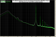
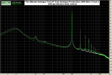
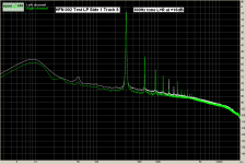
What you are pointing at? Vertical or transverse modulation?
http://www.diyaudio.com/forums/attachment.php?attachmentid=334646&stc=1&d=1362699535
http://www.diyaudio.com/forums/attachment.php?attachmentid=334647&stc=1&d=1362699535
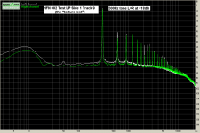
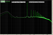
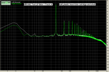
Or is it distortion related to modulation amplitude?
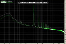
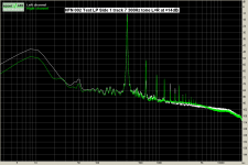
See some measurements. Formulas in that link predict distortion products. Measurements show this.
http://www.diyaudio.com/forums/attachment.php?attachmentid=334648&stc=1&d=1362699535
http://www.diyaudio.com/forums/attachment.php?attachmentid=334649&stc=1&d=1362699535
http://www.diyaudio.com/forums/attachment.php?attachmentid=334650&stc=1&d=1362699535
http://www.diyaudio.com/forums/attachment.php?attachmentid=334651&stc=1&d=1362699535
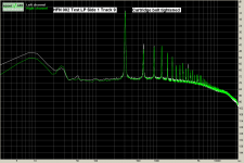
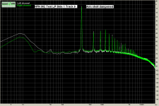
But there are a myriad “small” mechanical details that play a role too. See the following for some of them.
http://www.diyaudio.com/forums/attachment.php?attachmentid=334652&stc=1&d=1362699535
http://www.diyaudio.com/forums/attachment.php?attachmentid=334653&stc=1&d=1362699535
http://www.diyaudio.com/forums/attachment.php?attachmentid=334654&stc=1&d=1362699535
http://www.diyaudio.com/forums/attachment.php?attachmentid=334655&stc=1&d=1362699535
Skating force is another problem. If you like see here:Interesting article.
Not much on anti-skate though
http://www.diyaudio.com/forums/analogue-source/75389-think-thhow-puthhy-cat.html#post863681
Apart from antiskating force doesn’t match the change of skating force across the record radius, skating force varies with the dynamics of the recorded signal. Almost impossible to compensate for this
Scott,
Thanks for that RCA reference, makes me wish my Radiotron handbook hadn't been destroyed in flood! Still had information that was useful today, but that the way it goes when it rains into a rented warehouse!
A waterproof source
")
http://ia701507.us.archive.org/25/items/RadioDesignersHandbook/LangfordSmith-RadioDesignersHandbook.pdf
George
Attachments
-
 Ult T1.png34.2 KB · Views: 184
 -
 Ult s2 t4.png32.4 KB · Views: 184
 -
 HFN T6.png33.1 KB · Views: 174
 -
 HFN t7.png35.2 KB · Views: 177
 -
 HFN t8.png33.6 KB · Views: 177
 -
 HFN t9.png34.7 KB · Views: 41
 -
 HFN t9 bolts tightened.png33.2 KB · Views: 41
 -
 HFN t9 handle dampened.png33.9 KB · Views: 40
 -
 HFN t9 balsa insert.png33.9 KB · Views: 45
 -
 HFN t9 plastic inser light.png33.9 KB · Views: 46
Extrapolation of distortion below 1-2hz by curve fitting is inherently unreasonable, as the 1000 percent distortion question raises. Reminds me of the ultraviolet catastrophe.
jn
I concur. Tones of embarrassing stories in the literature with conclusions based on extrapolation/interpolation. I had placed a
in front! George
I think Wayne is suggesting doing something as an input transformer in some way similar. Perhaps he will clarify.OK, then it's the 1986 patent that I'm familiar with. I thought from this discussion that there was a cool input transformer trick.
I think Wayne is suggesting doing something as an input transformer in some way similar. Perhaps he will clarify.
There is a trick. Lundahl has it on their site. it allows the transformer to be much smaller. http://www.lundahl.se/pdf/7101.pdf However it doesn't work for this application (I asked).
The AP output transformer trick works but does require virtually perfect matching of the DCR of the transformer, hence the extra winding. I also asked about this and the Jensen guys did not recommend it, too difficult to execute and expensive. They make the transformer for AP.
Thanks Demian. Yes, after I thought a while I remembered the article somewhere about mic transformers, was it by Gaylord?
I understand that the latest Ap analyzers use a synthetic active transformer, which is o.k. in some cases but of course does not have galvanic isolation.
UREI used to license the patent for the copper resistor and used those transformers in some of their equipment.
IF I wanted to conform with market trends, I would design tube equipment.
Why follow building tube equipment market trends - spoken opposite, can we not see it with solid state as well?
Another point is that you only state with masurements. OK, they are fundamental but I'd like to see some objective statements regarding how it sounds. Why you don't compare both prototypes of the phono stage versions (with / without input transformers) and compare them in practical sonical tests. Would be informativ what the sonics results are. Maybe the version with input transformers sounds better?
Objective statements about how something sounds is an oxymoron.
Depends. If one uses a panel of listeners and collects rankings along various "subjective" quality axes (e.g., "brightness," "clarity," "image specificity," that sort of thing), objective conclusions can be drawn about subjective impressions. These data are often presented in "radar charts." ANOVA is your friend here.
That's not very practical for low volume items made for niche markets, unfortunately.
Objective statements about how something sounds is an oxymoron.
Not at all. It is very well possible to get objective judgements about subjective perceptions.
Actually, it can be argued that the only judgements about 'how something sounds' that have any value beyond just the single, personal, anecdotal judgement is an objective judgement.
jan
Last edited:
Reminds me of the ultraviolet catastrophe.
jn
Next gen masks will need a CO2 laser to create UV with a tin plasma, the estimate was 250KW in and 450mm wafers at $10Mil for a mask set.
Hurray
Me personal opinion is that punctuation and grammar should be in accordance with semantics, first.
Argued and arguemented can have two slightly off-set meanings.
It's only by having shared a pint, which enables me to re-arrange Jan's written text inside my feeble head, to make the meaning match up with his personality "blueprint".
Lingo can be a Dingo, mate.
I've not seen that, although it is an intriguing notion.
http://www.picovolt.com/win/elec/articles/Lepaisant_preamp-xfmrs_RSI.pdf
EDIT - That's DR. Hill's site (of the book fame). He does not seem to have added much for several years.
Last edited:
- Status
- Not open for further replies.
- Home
- Member Areas
- The Lounge
- John Curl's Blowtorch preamplifier part II