John, too much work to translate hundreds of pages, not responding directly to my questions, for the little i had read, even included in my question considering the all closed loop behavior.
Reformulating with an image, reducing gm of the input stage increase the efficiency of the ABS, but not the tire's grip.
Reformulating with an image, reducing gm of the input stage increase the efficiency of the ABS, but not the tire's grip.
Last edited:
Witch gives some advantage to bridged amplifiers.I'd wager "differential mode."
I thought it was "Dr. Lube"
Maybe it should be Dr. Cremlon, as another branch (one of hundreds) of his company now markets that product.
I'd wager "differential mode."
yes! So now with that knowledge, how do you design a power supply that minimizes diff-mode changes?
What characteristic would it have and what type of circuit has that characteristic?
-Richard
Here is page 9 (out of 20) of probably the best app. note on amplifier design that I have ever found. The top equation (20) is the KEY EQUATION for understanding slew rate and how to improve it. The left hand term is the definition of Slew Rate, or dv/dt
is proportional to 1/Gm of the input stage. The other terms are related to the input stage operating current and the gain bandwidth of the amplifier.
is proportional to 1/Gm of the input stage. The other terms are related to the input stage operating current and the gain bandwidth of the amplifier.
Attachments
The truce was short-lived.Pages 9 and 10 Esperado. You might just learn something.
As i said, i had read-it, ant nothing new, neither respond my question.
Yes, degeneration increase slew-rate of the input stage, thus a part of the delay. But the issue*is* the closed loop and it does the contrary of what we want : each stage faster than the previous one inside the loop.
You prefer open loop topology and you seem to allow artificial enhancement of slew rate *by the feedback* ? Seems contradictory.
CFA is a way to achieve high bandwidth of the first stage, *by design*. It does not replace having a fast power stage, where current is most demanded and load non mastered..
Last edited:
Virtual ground ? (Does not work so good because distortion.).how do you design a power supply that minimizes diff-mode changes?
An other solution (don't know the word in English) is crossed feedback between the two sides.
Last edited:
Virtual ground ? (Does not work so good because distortion.).
An other solution (don't know the word in English) is crossed feedback between the two sides.
There are several.... Master-Slave or dual Tracking regulator circuits are some that minimise differences between the + and - rail value.
Another is a simple way I introduced to audio is to put a large value C across the + to - supplies.
These means are not complex nor difficult to impliment and greatly reduces the circuit's need for extream PSRR's.
Thx-RNMarsh
Last edited:
Nice simple idea. kind of virtual ground addition. Half the value of each rail caps, in order to get the same C for the 3 ?Another is a simple way I introduced to audio is to put a large value C across the + to - supplies.
Cap between + & - followed by simple stabilization of each stage, like emitter follower ?
Last edited:
Nice simple idea. kind of virtual ground addition. Half the value of each rail caps, in order to get the same C for the 3 ?
Cap between + & - followed by simple stabilization of each stage, like emitter follower ?
A value equal to the rail shunt caps works best. This is easy to do on line level circuits.
On a SIM of a power supply for a 250W power amplifier, two 10,000 mfd caps were bridged with another 10,000 mfd cap (2X voltage rating, of course) and when an 8 ohm load was switched across one rail or the other, the delta or rail voltage difference was minimal. A physical supply was made with same results. To do same with a high current tracking regulated power supply would be impractical in a consumer product.
When the delta is zero, there is no difference in rail voltages and therefore, no affect on the circuit and is as if the PSRR was very high. This allows Current feedback circuits to be more effective in audio circuits.
Thx- RNMarsh
Christophe
Richard means the cap at the output of the psu.
It works best when placed right at the load(s). A cap across +/- at each amplifying stage or each op amp IC
In practice, the capacitance of this C can be small (1/10th of the rail to ground caps or even less) since the unbalanced currents it has to deal with are small compared to the working rail currents.
George
I was thinking about a 2 channels power amp.Richard means the cap at the output of the psu...OPA
WIl try at each amp board rails. (Ça peut pas faire de mal
I have pain to figure out the currents of such a configuration in dynamic mode, i don't know why.
Last edited:
Gpapag is correct: Place the cap where the amplifier needs it... at the output of the regulator. If no regulator -- as with a pwr amp output stage -- then place it across the rectifiers or the main filter caps.
With opamps, the value can be smaller of course as the dynamics on the +/- rails is smaller. But even so, a larger value with bypass works well.
Thx-RNMarsh
Note: Reason for using larger value --> besides cancelling D-M noise and transients on the rails, if one line went low, the bridging cap will discharge into that line to maintain the same level as before. Tendancy is to keep the + and - levels to be equal. The line may be drawn down but both rails will always be maintained at the same value.
Last edited:
Would not be all improvements exactly the same, if You simply doubled value of existing capacitors, what is trivial?? And added bridging cap seems to dynamically push rail with lower loading to higher output voltage (adding ripple)..On a SIM of a power supply for a 250W power amplifier, two 10,000 mfd caps were bridged with another 10,000 mfd cap (2X voltage rating, of course) and when an 8 ohm load was switched across one rail or the other, the delta or rail voltage difference was minimal.
Last edited:
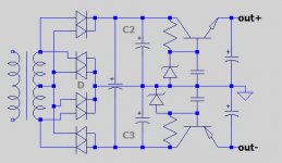
As this is the Blowtorch thread, I might let you in on a design 'secret' that is in each of the power supply modules (up to 4) in the Blowtorch power supply.
We used 3 power caps as well, but we separated the single cap from the dual caps with a damped dual choke. This way, the input cap bears the majority of the input surge, and the 2 larger (in value) caps do most of the ground return.
We used 3 power caps as well, but we separated the single cap from the dual caps with a damped dual choke. This way, the input cap bears the majority of the input surge, and the 2 larger (in value) caps do most of the ground return.
- Status
- Not open for further replies.
- Home
- Member Areas
- The Lounge
- John Curl's Blowtorch preamplifier part II