We are talking about bandwidth extension at a relatively elementary level. To be sure, some companies who worked in isolation, like Mark Levinson, after 1977, may have found high frequency bandwidth limiting useful to cover over RFI and even slew rate limit issues.
The high bandwidth argument goes back many decades, primarily to Harmon Kardon (of all companies). They found extended bandwidth useful and tended to strive for it, even within the engineering limitations of 35+ years ago.
In 1978, I remember sitting in conference at HK with Matti Otala and the HK managers, where he wanted to introduce a 50K 2 pole discrete filter to be placed in front of the new amp design we were working on. The HK managers balked at the suggestion, as they had done listening tests previously that showed that even wider bandwidth was sonically important. I attributed that to the use of ceramic capacitors used as filters in their earlier tests, but I can't be sure. In any case, this 'opinion' bounces back and forth like a rubber ball, and much of it depends on 'time and place' what equipment, and the potential of the sources to give extended frequency information.
Back in 1978, I decided that the electronics MUST pass, at minimum, a 10us rise-time square wave without adding significant distortion at all levels to either the waveform (phase) or non-linear IM products . If you can't do that, then some microphones can be faster and cause problems, some 30 ips tape recorders can be a problem, and finally, mistracking artifacts from MC phono cartridges can be a problem, especially to the final power amplifier. It is interesting that the best analog tape machines, the best microphones, and now SACD or 24/96 or more, can put out a 10uS rise-time square wave, and therefore we either design super fast amps or preamps, or we bandwidth limit above this 10us risetime, limit.
RFI insertion that DOES HAPPEN often, is harder to get a number on, as far as effective bandwidth limitation, and I would vote for 100KHz. if practical, or higher like 250KHz if possible.
The BLOWTORCH has an intrinsic 350KHz bandwidth limit, for example.
Ed, maybe not exactly pertinent but with power transformers being discussed again maybe its time to answer your own question (post 33160)
Thanks
-Antonio
Give me a day or three to finish taking all the data points. I am testing a nice assortment of transformers. (Early answer is out of phase passes less noise.)
That is what i said.
Christophe
Thank you for confirming the acoustical effect of phase change.
Regarding digital filters, if I read you correct, you say that they do not produce phase changes.
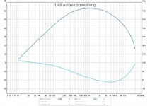
Here is the measured freq (upper trace) and phase response (lower trace) from the output of a FIR digital bandpass filter (-3db at 3300Hz (LP) and 320Hz (HP), both LR 12db/oct ).
As you see, phase does change with these digital filters.
Perhaps it is only IIR filters that do not change the signal phase as you say.
George
Attachments
The input signals to all products should not be greater than the BW of the amp. Notice that the frequency response tests on M-Levenson products had rolled off high freq just above audio range/ 20Khz. This was done at the input... Limiting the distorting affects of EMI/RFI and unwanted HF/RF from entering the amps/preamps. Thx -Richard
In commercial broadcast gear the standard was input and output transformers on everything. RFI being a very big issue as studios were often located next to transmitters.
An interesting innovation (C.A. 1970) was the use of an opamp based low pass filter/differential input and still the use of an output transformer. At first look this seems silly as the input transformer costs less than an output transformer. But when you factor in the input impedance matching requirements Dick mentions you might see why using a floating output transformer offered many advantages. (This will be a point of issue for some.)
I have had projects where send and receive transformers were required to get enough balance to keep the noise down to an acceptable level.
For "Pro" audio gear you can of course get balanced lines from electronics but it is the isolation that is often required.
In domestic use it is allowed for there to be a few volts between safety ground and neutral. In large arena PA systems this can go above that. The issue becomes the degradation on the CMRR when you have the common mode voltage approaching the power supply rails. On +/- 15 volt rails that is 10 volts RMS. (Or 5 volts on each ground 180 degrees out of phase.) Once above that gear gives up. So that transformer isolation can be quite useful in pro applications.
In domestic use it is rare that you have 5 volts of AC between the ground and neutral.
As hitsware said, it's mostly a semantics thing. Usually makes no difference, but AC power is the one case where it matters (some.... ). Power in North America at least is strung around in 3 phase lines and then fed single phase, 2 polarities to residences. Phase refers to timing and polarity to voltage.
Thanks,
Chris
Interesting point, one could say opposite polarity is 180 degrees of phase, but you are correct in the literal sense a Delta-Wye transformer converts the three phase transmission into single phase residential service. It is still correct to point out that 110/120 is only at the point of use.
Interesting point, one could say opposite polarity is 180 degrees of phase, but you are correct in the literal sense a Delta-Wye transformer converts the three phase transmission into single phase residential service. It is still correct to point out that 110/120 is only at the point of use.
In this neck of the woods, three phase wiring is on the main roads, and in the residential roads, only one phase is distributed. They use what is called a single bushing transformer, as only one hv bushing is present. The utility is charged with balancing loads within a residential area.
On the west coast, they take two of the phases on the top of the pole to the transformer, and use a two bushing transformer.
For most commercial 3 phaseon this side of the woods, there will be three transformers on the pole, each connected between a hv phase and neutral/earth.
jn
An exhaustive search will no doubt find numerous solutions, after all we could be in Brazil where 110 and 220 share the same connectors from county to county (27, I think). I realize our installation is recent and an experiment since we buy in bulk for 41 households with no submetering.
Our grid waste is 6% plus minus a little, I wonder how much more is added by using 110 vs 220 in some places.
Last edited:
George, there is two types of digital filters. The ones i was reffering too is called 'linear-phase'.As you see, phase does change with these digital filters
I googled for you and found this: Linear Phase vs. Minimum Phase EQ
I would had talk about group delay, btw.
Last edited:
It is about quantity of coper for the same power, and some old formula, may-be still in us:e P=RI²Our grid waste is 6% plus minus a little, I wonder how much more is added by using 110 vs 220 in some places.
") ?
?While i was in Google, i found that, in France, it was in 1955 that we began to move from 127 to 230/240 V. As EDF (French electicity company, a state service) was changing for free the equipments of the customers impacted by this change during five years after that, i'm happy this does not happened later. Imagine, today, if they had to change all the Blowtorch ?
Last edited:
I recall the distribution losses are about 9 to 10%, that amount could be saved by going superconducting.Our grid waste is 6% plus minus a little, I wonder how much more is added by using 110 vs 220 in some places.
I've no idea what the portion of that is after the substations.
jn
I just found the distribution losses in France are estimated around 2,5 %. It's worth risking electrocution.I recall the distribution losses are about 9 to 10%,
I recall the distribution losses are about 9 to 10%, that amount could be saved by going superconducting.
I've no idea what the portion of that is after the substations.
jn
NEMA says 6.5% but the expense of recaptuing all of that with current superconducting technology would be a bit ridiculous. I found some folks lumping generation efficiency into the distribution loss, talk about bias.
A funny story. I live in a supposedly "ultra green" community and we buy our power in bulk at around .$0.10 a KWH. We decided that we would take the opportunity offered by (I forgot which) gov. agency to pay 1 cent extra to guarantee wind or solar as our source. When it came to decide which people locked horns for and against both technologies and nothing happened.
Last edited:
The different figures being quoted for 'distribution' losses in different countries might be complicated by the distinction which power engineers may draw between transmission and distribution. The former is long distance (in the UK, the National Grid and SuperGrid e.g. 275kV and 400kV). The latter is local (132kV and lower). Roughly speaking, the Grid is multiply-connected while local distribution is more likely to be a set of independent branches.
So what I am saying is that to compare like with like you need to add transmission losses to distribution losses, if the two are distinguished.
So what I am saying is that to compare like with like you need to add transmission losses to distribution losses, if the two are distinguished.
Less current to transfer, less impedance losses.
Yes, but they also convert to and from DC (!). Pictures of the SCR's will blow your mind. People look like ants, as the saying goes.
Thanks,
Chris
Another subtle effect in the power distribution differences between Europe and the US is 3 wire 3 phase vs 4 wire 3 phase, it is a while ago that I had to deal with it, but as it is true 3 phase transformers everywhere in the UK and we use a dedicated Neutral wire as well as the center wire, we have 230/240 V in houses and 415 as the next step up (delta-wye transform) but in the US it is all 3 wire 3 phase, so an imbalance in power consumption between the phases leads to a phase error and waveshape error in the US but it leads to neutral current in the eurpoean model, no free lunch either way...
Wrinkle
Wrinkle
One of the early d.c. conversion substations was located in Sylmar CA, and I understand it didn't look pretty after the 1971 earthquake.Yes, but they also convert to and from DC (!). Pictures of the SCR's will blow your mind. People look like ants, as the saying goes.
Thanks,
Chris
I've been told that the main reason to use half million Volt DC long lines is because, even at 60 Hz, too much would be lost by radiation from the big antenna. (!)
Thanks,
Chris
I thought that the UK supergrid was still AC, it is only the Power share with Europe in undersea cables that is DC.
Yes, but they also convert to and from DC
I am sorry I have not followed the debate, my remark was related to power line VHV ac transfer.
- Status
- Not open for further replies.
- Home
- Member Areas
- The Lounge
- John Curl's Blowtorch preamplifier part II