Attache is the inverted Fletcher Munson type curve I showed yesterday. I have added another "curve" to it. So what does this represent?
Capacitive impedance vs. frequency. (blue line). Or opamp OLG gain.
Last edited:
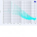
Skin affect nomogram
I didnt intend to show anything about the B field. I'll trust you on the proxy explaination. For others, attached is a nomogram for determining the skin effect (steady state and transient). Thx-RNMarsh
From Pulsed High Magnetic Fields by H.Knoepfel

http://www.google.com/url?sa=t&rct=j&q=tubular%20conductor%20parallel%20filament&source=web&cd=1&sqi=2&ved=0CC8QFjAA&url=http%3A%2F%2Fwww.doiserbia.nb.rs%2Fft.aspx%3Fid%3D1451-48691001013F&ei=_uz_UMC2K7Sp0AHprIHACA&usg=AFQjCNFGkFIQlnxKNwN49oLehmBETsY7dw&bvm=bv.41248874,d.dmg
Your first figure is electrostatic potential, not magnetic field density. Static B field in a cylindrical conductor is exactly straight line, zero at center max at surface. Once time varying is introduced, the straight line will be depressed at center, reinforced at surface, and certainly not straight..
Oh, while I'm at it. The current density of the core of a coax goes to the surface, we call that skin effect, think of it as the current redistributing to lower inductance, that being the 15 nH per foot inductance consistent with a cylindrical conductor. The current density of the shield goes to the inner surface...that is NOT skin effect, it is proximity effect as a consequence of the magfield being generated by the core wire. When asymmetrical core to shield occurs, this proximity effect will force the shield current to redistribute such that magfield outside the shield goes back to zero, and the current takes the path of lowest inductance (reactance).
jn
I didnt intend to show anything about the B field. I'll trust you on the proxy explaination. For others, attached is a nomogram for determining the skin effect (steady state and transient). Thx-RNMarsh
From Pulsed High Magnetic Fields by H.Knoepfel
Last edited:
No, sigma is conductivity - a material property. Current is I; current density is J.jneutron said:Lambda has current embedded, although the authors do not state it..sigma.
Which I repeat.Actually, that is incorrect.
However, my explanation is also in error. I believe sigma is the sheet conductivity, needed for calculation of eddy current density.
The authors of the paper specifically state in the setup that they start with a sinusoidal current of angular frequency omega and rms current I.. They are specifically looking to solve for the integrated resistance ratio, and have bypassed calculation of the time varying resistance. AND, of more specific note, their final calculation of resistance ratio is independent of current direction.
This calculation can easily be converted from one of rms value and frequency to slew rate, but they are not interested in the time variation, only the rms.
These equations would be useless for signals which are of constant frequency but arbitrary slew rates, such as is typical of switchmode supplies.
jn
edit: I see we cross posted..
Last edited:
Capacitive impedance vs. frequency. (blue line). Or opamp OLG gain.
The winner.
Now one more item attached. This is the spectrum of the ripple on a single capacitor power supply. How does this spectrum differ from the rolloff that would be expected from the single capacitor filter. (It has a single 470 uF filter capacitor.)
Attachments
Agreed.jneutron said:I believe sigma is the sheet conductivity, needed for calculation of eddy current density.
No. They have not calculated the "time varying resistance" because it does not exist. Their calculation does not give the "rms" resistance, but the resistance. It does not vary with the AC cycle. The current density does not vary at twice the frequency, as you still appear to be claiming. At a particular point, the current density has a fixed amplitude and a sinusoidal variation.jneutron said:The authors of the paper specifically state in the setup that they start with a sinusoidal current of angular frequency omega and rms current I.. They are specifically looking to solve for the integrated resistance ratio, and have bypassed calculation of the time varying resistance.
This calculation can easily be converted from one of rms value and frequency to slew rate, but they are not interested in the time variation, only the rms.
No. Provided any non-linearity in the circuit is small, which will normally be the case, you simply use a combination of superposition and Fourier theory. Each frequency component in the total current will have its own skin/proximity effect, based on frequency alone. You just add up all the contributions. Higher frequency components will be nearer the surface. This means, of course, that at a particular point within the conductor the current density waveform will not match the total current waveform but will have boosted HF. The 'many parallel inductors and resistors' model illustrates this.These equations would be useless for signals which are of constant frequency but arbitrary slew rates, such as is typical of switchmode supplies.
The winner.
Now one more item attached. This is the spectrum of the ripple on a single capacitor power supply. How does this spectrum differ from the rolloff that would be expected from the single capacitor filter. (It has a single 470 uF filter capacitor.)
-40dB/dec vs. -20dB/dec
You are saying you have added 50 ohm load.
At a fixed point, the current density is the summation of the sine drive current added to the eddy current caused by the external wire. Eddy currents are proportional to the rate of change of the flux through a conductive surface.No. They have not calculated the "time varying resistance" because it does not exist. Their calculation does not give the "rms" resistance, but the resistance. It does not vary with the AC cycle. The current density does not vary at twice the frequency, as you still appear to be claiming. At a particular point, the current density has a fixed amplitude and a sinusoidal variation.
Um, they've modelled for zero thickness. And the best switchmode people on the planet don't seem to be able to understand how simple you claim it is..No. Provided any non-linearity in the circuit is small, which will normally be the case, you simply use a combination of superposition and Fourier theory. Each frequency component in the total current will have its own skin/proximity effect, based on frequency alone. You just add up all the contributions. Higher frequency components will be nearer the surface.
Ed needs to redo the test, but use 1 or 10 ohm resistors instead to increase the effect multiple orders of magnitude. 120 or 150 dB down isn't gonna float anybody's boat. If it goes up, voila.. If not, ditto.
jn
Ohh? I thought we had agreed here that measurements say nothing about sound quality? Are you now saying that the rank of 7th determines the rank of sound quality, even if it is below the -110dB audibility threshold John gave?
My personal level of interest and discernment isn't high enough to rank something as subtle as line level monolythic op-amps, but PMA gave his opinion, which I greatly value.
Any causal statement about correlation between a specific measurement and "sound quality" is surely premature. But we're all trying to get there. Yeah Us.
Thanks,
Chris
You may choose to call them eddy currents, but the net result is that the current density is everywhere sinusoidal at the applied frequency. The geometric distribution depends on frequency alone. For non-sinusoidal waveforms Fourier and superposition is all that is needed.jneutron said:At a fixed point, the current density is the summation of the sine drive current added to the eddy current caused by the external wire. Eddy currents are proportional to the rate of change of the flux through a conductive surface.
Yes, in order to be able to obtain an analytic solution. This simplifies the maths by eliminating skin effect; it doesn't change the physics.Um, they've modelled for zero thickness.
I have never met any of these gentlemen, so I have no idea what they think or whether they have the same misunderstanding as you.And the best switchmode people on the planet don't seem to be able to understand how simple you claim it is..
So far, the only peer-reviewed paper you have produced to support your claim actually completely destroys it. I must admit I was puzzled when you offered the link, but I did wonder whether you might have misunderstood the paper. It seems you did.
Please don't keep reasserting ideas which are false. Find some genuine supporting information, or admit that you are mistaken.
You may choose to call them eddy currents,(the author chose to) but the net result is that the current density is everywhere sinusoidal at the applied frequency.(the proximity driven currents are proportional to the drive current slew rate) The geometric distribution depends on frequency alone. For non-sinusoidal waveforms Fourier and superposition is all that is needed.
Yes, in order to be able to obtain an analytic solution. This simplifies the maths by eliminating skin effect; it doesn't change the physics.(never said it did. You stated depth vs frequency, the author didn't, but used thinshell)
I have never met any of these gentlemen, so I have no idea what they think or whether they have the same misunderstanding as you.(it's not a misunderstanding, they can't duplicate the simplicity of your argument when characterizing proximity losses at varying slew rates. The best most can do is emperical values.)
So far, the only peer-reviewed paper you have produced to support your claim actually completely destroys it.(actually, claiming such doesn't mean it is so. As the authors stated up front, they simply used the integrated form with no intent to determine redistribution as time varying.). I must admit I was puzzled when you offered the link, but I did wonder whether you might have misunderstood the paper. It seems you did.(see last statement.. starting with an assumption doesn't mean the assumption is rule)
Please don't keep reasserting ideas which are false. Find some genuine supporting information, or admit that you are mistaken (sheesh, the first person to even try the test finds 2nd harmonic in the result, but I guess test results mean nothing. Let's convince Ed to drop the resistor value and try again..) .
btw, I certainly am finding lots of proximity modulation for organic pores and magnetic proximity resistive detectors..sometimes, google is your friend..other times...
jn
Last edited:
Where do they state they had no intention to determine a time varying distribution? There is no hint that I can see that they thought they were using a time-averaged form anywhere. Please identify their statement which you believe says this.jneutron said:As the authors stated up front, they simply used the integrated form with no intent to determine redistribution as time varying.
There are vast numbers of postings in this, and the previous thread bemoaning that the standard measurements don't give enough of the story to know what will "work" and what won't. Yet rather than focus of how to extend the measurement regime to get more useful numbers, to be more able to predict the real world performance of an actual product, the conversations grind on and on and on about the same old, relatively easy to produce, numbers, debating the merits of their relative sizes.
The sting in the tail always is, of course, a fairly general agreement, as an appendix to the discussion, that those numbers mean very little in the subjective world of audio.
Talk about wasted energy - if I come back here in 5 years time will I see exactly the same conversations occurring ... a "song" playlist on endless repeat ...
Frank
I can't find the term "eddy current" in the text. Are we reading the same paper?jneutron said:the author chose to
I have suggested putting distorted music through a good psychoacoustic encoder to see what the model chooses to keep in the compressed file - surely most of what the psychoacoustic compression encoder wastes bits on is more likely to be "clearly audible"?
the Filipović paper does explicitly invoke superposition - implying Linearity of EM is a base assumption - may be hard to find papers that don't use it to frame the math
I did run across Giulliani "On electromagnetic induction" 2001 several versions, the 2009 publication costs money - he adds in the Lorentz force term which I think should then model "ordinary magnetoresistance" (rot = curl was confusing)
Last edited:
""Currents of angular frequency ω and r.m.s. value I""Where do they state they had no intention to determine a time varying distribution? There is no hint that I can see that they thought they were using a time-averaged form anywhere. Please identify their statement which you believe says this.
I can't find the term "eddy current" in the text. Are we reading the same paper?
J2 is eddy currents.
jn
Talk about wasted energy - if I come back here in 5 years time will I see exactly the same conversations occurring ... a "song" playlist on endless repeat
That's because it's not a technical discussion where evidence answers questions with finality. This is about fashion and faith, which are incapable of being decided. Russell's criticism of Aquinas comes to mind.
Bertrand Russell said:He does not, like the Platonic Socrates, set out to follow wherever the argument may lead. He is not engaged in an inquiry, the result of which it is impossible to know in advance. Before he begins to philosophize, he already knows the truth; it is declared [by his faith]. If he can find apparently rational arguments for some parts of the faith, so much the better; if he cannot, he need only fall back on revelation.
That is defining the total current. No time integral is stated or implied. To define a sinusoidal current you need to specify its frequency and amplitude. This they do. Amplitude for AC currents is usually specified either as peak or RMS. They use RMS.jneutron said:""Currents of angular frequency ω and r.m.s. value I""
It is slightly puzzling, as EM theory usually uses peak current, but it has no significance for what you are saying. So there is nothing in the paper to say that they are using a time average. This is, of course, because they are not using a time average.
That may be so, but the authors do not say so; your assertion that they do is therefore false. However, we are not arguing about what something is called but what it is.J2 is eddy currents.
You are going to have to try harder.
It may turn out that the information derivable from measurements and the information derivable from formal listening are separate, but hopefully related, interpretations of a third underlying function. I sometimes interpret what John Curl is trying to teach here as a plea to study the underlying function for its own sake. Topology, ancillaries, intrinsic properties, etc.
And, although it's almost an object of faith, where has it ever been shown that because an effect has very small numbers, maybe even below the noise floor, that it must be inaudible? That looks plausible, but it lacks foundation.
Thanks,
Chris
And, although it's almost an object of faith, where has it ever been shown that because an effect has very small numbers, maybe even below the noise floor, that it must be inaudible? That looks plausible, but it lacks foundation.
Thanks,
Chris
And, although it's almost an object of faith, where has it ever been shown that because an effect has very small numbers, maybe even below the noise floor, that it must be inaudible?
It hasn't and it can't be, as a matter of logic. What can be demonstrated, in principle, is the audibility of some of these asserted "problems." What data exists don't demonstrate it (beyond well-known variables like frequency response, level, clipping, gross distortion...), and the folks who assert it are singularly unwilling to provide anything beyond "because I say so and I got some nice reviews in a magazine."
Once something is shown to be audible, then there's data to work with, otherwise people would be wasting a lot of time chasing after ghosts when any nut-ball with a keyboard can claim that (for example) the direction of wire makes night and day sonic differences to anyone who isn't deaf.
- Status
- Not open for further replies.
- Home
- Member Areas
- The Lounge
- John Curl's Blowtorch preamplifier part II