That is my experience too. For the same reason, i found some heads, if i remember well, had a better 'opened sound' loaded with 100K instead of 47, depending of the capacitance of the wires..Flattening the peak added damping as well and combination always tended to make the sound 'dull'
I always liked the midrange flat. -Thx RNMarsh
The sound was very different from one head to an other, one arm to an other, changing with stylus pressure, kind of diamond used, and even plate's resonances...
Despite my automated radial arm turntable modified with a carbon fiber cleaning brush on the chariot, it is always scary to manipulate those precious vinyls.
I'm glad to the Digital industry to get rid of all those problems.
Hi Pavel,
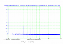
What measurement equipment are you using? It doesn't appear to be your normal plots.
Thanks,
Mogens
Hi Mogens,
already replied here:
http://www.diyaudio.com/forums/anal...ch-preamplifier-part-ii-3328.html#post3337110
I bought a new software to get reliable results in SNR and NL. It also generates clean signals (ref. Fs and FFT length) and uses rectangle window, more in the manual.
Last edited:
And finally, OPA637. Low distortion, low noise and low sensitivity to interference. My vote
No 7th!!")
I guess it's suitable for mid-fi. The only way it could work for High End is to hide it inside some mysterious box and tell a good story.
I guess it's suitable for mid-fi. The only way it could work for High End is to hide it inside some mysterious box and tell a good story.
A good story is all we want, isn't it?
Time to confess, now.
In 70s, our boss was putting much pressure on us (r&d office) to offer some quadraphonic feature to our market (hype at this time, while no quadraphonic records were available) .
So we added in one of our amplifiers some resistances to feed 2 extra loudspeakers to be situated back to the listener's place, with the difference signal of the main amplifier (each added loudspeaker in phase opposition).
L, R, (L-R),( R-L).
As we were very shamed with it, the resistances where hidden in resin. Of course, we let the marketing department free to compose the marvelous story and benefits of our mysterious black box.
I hope this will be forgotten or forgiven the day i will do a job ask at the Paradise's door.
jn
You have all my respect when it comes to EM.
But this generation of harmonics didn’t cling to me from the start.
I have some days now reading back Heaviside’s Electromagnetic Theory and I didn’t find any supportive evidence. The closest to the subject is para 191, pages 344-349 (*) of Vol. I (I haven’t looked at his Electrical Papers yet).
The explanation you give here (in bold letters)
is central to your reasoning.
I want to ask:
1. Is what you suggest a result of experiments or of theory?
2. In case of experiments Is it possible that harmonics are caused by (a) heat diffusion velocity effects in the conductors and/or (b) attraction - repulsion forces causing minute distance modulation btn conductors?
.
George
Answers.
1. Both. Most people would just be happy measuring Ls/Rs, and assuming that Rs is simply a frequency born effect. It's a reasonable approximation, and one generally used with switchmode supply modelling for dissipation within the conductors due to proximity. My applications are significantly more shall we say, sensitive, to the effect.
2. I would assume so, but the level of effect has a huge negative exponent. The thermal mass of most materials and the thermal conductivity cause very slow diffusion velocities. Even for copper, it is quite low.
My understanding is that if electr. conductivity is very high (and magn. permeability is 1), this time varying resistance will be synchrounous and with no delay in respect with the excitation, thus it will affect current only in amplitude - and this a little- and not generate new frequencies
The rate of change of the magnetic field is the time derivative of the current. So the resistance will be maximum while the current is passing through zero in both directions.
the resistance doesn't change, the (partial, spatially varying) mutual inductance with the proximity current causes emf (also spatially varying) that appears to redistribute the current through the sheet of the physically distributed resistance (quite accurate)
very close. The "shoved to one side" is actually the result of the summation of currents... The current within the resistor summing with the surface currents being generated within the conductive film of the resistor, faradays law of induction. This is why I also mentioned the amplitude modulation of the resistor voltage as a result of a non correlated time varying magnetic field attacking the resistive element.)the appearance of the current "being shoved to one side" only happens with identical waveforms in the wire and the sheet resistance
Do not confuse skin based effect with proximity caused by an external magnetic field. Faraday seems to disagree with your assertion.If it is rate of change of current, as jn asserts, rather than frequency, as the textbooks say, then the penetration of current would vary through the cycle. This would mean that any RF or microwave system would generate second harmonic whenever RF encountered a conductor, as the current density would be varying at twice the frequency. I am not aware of this phenomenon ever being reported.
It is important to consider the polarities of both the current and the current derivative. You are not.I am baffled why jn continues to assert something which is simply false. The maths is quite clear: the geometric distribution of current depends on frequency alone.
You use a higher slew rate current as an example, but then claim it's frequency and not slew rate??.Where a sharp pulse is concerned then the individual frequency components (e.g. f, 3f, 5f etc. for a square wave) each have their individual exponential decay into the conductor. This means of course that a sharper pulse may penetrate less but this is because of its higher frequency components not its greater amplitude.
I am getting bored with this. There is a point beyond which it is not worth repeatedly asserting known EM theory to someone who rejects it.
Having quite a bit of experience in theory, modelling, building, and testing this kind of stuff, I find the assertion that I reject EM theory as funny.
Perhaps you should contact someone who does this other than me . Sullivan at Dartmouth would be a good one.
jn,
That would help but I think I'm following your basic argument just not quite how it produces a second.
If one accepts the dI/dT dependency and that this effect only increases the crowding resistance then I can understand how for a sinewave this would result in cos modulation from the dI/dT and the absolute value to account for only increasing resistance.
But from there I see this modulation producing steeper slopes around the cross-overs, local minimums at the peaks, all symmetrical between positive and negative going cycles of the sinewave. Why wouldn't this symmetry measure as a dominant 3rd?
Because the current within the resistor swaps polarity at the exact same rate as the current which drives the time varying field. The end effect is the current will be "pulled" towards the driving wire during both polarities.
I think DF's problem is he (and others) are thinking along the lines of Hall effect. When the modulating field is the same signal as the resistance current, you have to rethink the problem.
jn
Last edited:
Well, PMA, thanks for your discovery of the OPA637. Unfortunately it is 5 times the price of what I am using, and is 10dB noisier. However, for MM cartridges ONLY, it is just about perfect.
I don't know why I am constantly being confronted about the 'marketing' of my designs. It's true! Manufacturers MARKET my designs. They praise my name to the stars, and give many of my designs attributes that I never thought of, and if I look at their 'claims' seriously, I sometimes wince. However, I don't participate in marketing, seldom confer with the 'marketeers' and even then, only on technical matters.
I am told to: Get out of the way and to leave the marketing to others. I am never supposed to criticize my own designs. My bosses send me nasty letters when I do so.
So there it is: The free market of audio with different groups 'hyping' their designs, hoping that they will get enough sales to keep the company going in this economy. I'll participate in none of it.
What I HAVE tried to show here, is the 'subtle stuff' sometimes even ignored by the manufacturers of my designs, to their own peril. Because IF they ignore the 'subtle stuff' the audio product will often FAIL in the marketplace, both with reviewers and the general public.
Enough 'failures' and there is no further company. I have been threatened with dismissal several times for the 'failures' but I have always been able to 'save' the design concept at least with a 'successful' almost identical design made with my 'subtle changes' added.
This is true of the JC-1, JC-2, and the JC-3 from Parasound. However, other designs, even initially done by me, are not in my direct control, and can be compromised by the builders in Taiwan, to save, time, money, whatever. Yet, the examples of the JC branded products usually trickles down to the less expensive models, and usually a pretty good product is produced, thank goodness. This is my reality, accept it or leave me alone, please.
Very true
Now lets try a simple question. If my PSSR at 120 Hz is 90 dB, There is .1 V P-P ripple (120 Hz.) on my negative supply, none on the positive supply and my gain is 60 dB. Can you predict from the data sheet what the output ripple will be?
Can you offer a value based on experience?
ES
Never looked at anything that bad. I don't see the point in discussing something no one would ever do unless they are learning for the first time.
I guess it's suitable for mid-fi. The only way it could work for High End is to hide it inside some mysterious box and tell a good story.
I haven't seen preamps where line stage has 40dB of gain lately.
What happens when you reduce the gain to 20 or 10dB? Still no 7th?
Thank you .If there is anyone interested, here is the complete measurement of opamps + schematics.
Low noise but high distortion and higher order distortion. The last one in my test
Too bad this is the last one in this test, was hoping you had some opa211 laying around.
I am sorry I wrote OPA627 in the 1st chart in the zip file, it was OPA637 as correctly stated at the measurement page.
vacuphile - I do not have OPA211, sorry.
elektroj - if I reduce gain to 20dB or 0dB, there is already no 7th, but I am unable to measure distortion and noise then, for it goes below sound card threshold.
vacuphile - I do not have OPA211, sorry.
elektroj - if I reduce gain to 20dB or 0dB, there is already no 7th, but I am unable to measure distortion and noise then, for it goes below sound card threshold.
I don't know if this is an appropriate time, but a great deal of confusion has been generated about: not only my designs, but low noise design as well.
I personally have been working on low noise design of phono stages since 1966. I really hoped to make a solid state pre-preamp to replace the Ortofon transformer that I was using. When I read that I could PARALLEL devices, I realized that I could get almost any voltage noise floor that I was willing to invest in. However, I needed more understanding of solid state tradeoffs, before I could advance.
In 1967, I visited Ortofon, in Copenhagen while on a tour of Europe, and asked them for the specifications of the transformer that they originally included, that was mounted directly BEHIND the cartridge body. This added MASS to the phono cartridge, and the transformer was necessarily very small, (compromised) as well, at the time.
I was shown that future transformers would be mounted OUTBOARD so the 'mass' problem was fixed. Then I mentioned that I was still thinking of building a solid state 'transformer eliminator' and they 'showed me the door' literally, claiming that their best engineers had claimed it impossible, and therefore I was just some 'nut' wasting their time.
Well time passed, and within a few months, I got use of a QuanTech noise analyzer, and I got busy. It took years to make a 'truly unique' ultra low noise design, but I had the problem solved in 1968, by using 4 paralleled 2N4403 or even better, 2N4405 (to-5) transistors in parallel, to get an equivalent noise of about 10 ohms or so. The problem then, was HOW to follow the input stage with something elegant, rather than just an add-on circuit. That took much longer. Ultimately the Levinson JC-1 appeared with a rated noise of 0.4nV/rt Hz noise at the NY AES in 1973. Of course, nobody believed it, just like today. However, it was a VERY SUCCESSFUL, if limited design (dynamic range wise) and held its own for several years, almost a decade.
I could go on, but here is the point: Low noise design has been known about (what to do) for many decades. The problems are: Which devices, both affordable and available are REALLY LOW NOISE for the application they are to be used?
Second: Can you make the rest of the design both well performing, and even elegant?
Third: Can you avoid 'problematic' parts like input caps and biasing diodes that only add to the distortion/noise of the unit?
If you can do all three, you have a good chance of making a low noise, successful audio design.
Last edited:
It entertained the mass, and did no harm in epoxy it MAGIC . The buyer saw it as value no harm to them you will be forgiven.Time to confess, now.
In 70s, our boss was putting much pressure on us (r&d office) to offer some quadraphonic feature to our market (hype at this time, while no quadraphonic records were available) .
So we added in one of our amplifiers some resistances to feed 2 extra loudspeakers to be situated back to the listener's place, with the difference signal of the main amplifier (each added loudspeaker in phase opposition).
L, R, (L-R),( R-L).
As we were very shamed with it, the resistances where hidden in resin. Of course, we let the marketing department free to compose the marvelous story and benefits of our mysterious black box.
I hope this will be forgotten or forgiven the day i will do a job ask at the Paradise's door.
Never looked at anything that bad. I don't see the point in discussing something no one would ever do unless they are learning for the first time.
Would you be happier with 300 uV?
Hi Mogens,
already replied here:
http://www.diyaudio.com/forums/anal...ch-preamplifier-part-ii-3328.html#post3337110
I bought a new software to get reliable results in SNR and NL. It also generates clean signals (ref. Fs and FFT length) and uses rectangle window, more in the manual.
Hi Pavel,
Thanks

Better get those eyes checked.
Mogens
- Status
- Not open for further replies.
- Home
- Member Areas
- The Lounge
- John Curl's Blowtorch preamplifier part II