The guy who invented the 'Sound of cables ' ?with Noel Lee
Another photo. RIP both of these guys.
When did Jim B pass away?
There is no more evil thermal effects in audio engineer's Paradize.Another photo. RIP both of these guys.
JC, if you believed in him, you should have read his datasheet.
The best OPA or even Golden Pinnae stuff, hand carved from solid Unobtainium by virgins, won't stop poor design from losing 10dB of signal noise .. or introducing distortion and instability with poor decoupling and layout.
Mostly explained in the AD797 datasheet.
")
Yes but there are several MM input pre-amps in production that use equivalent bi-polar parts from us or LT, and then there was one from one of John's white hats (Mitch Cotter) but I think that was MI (Grado). You could use the 1977 National app. note and add A weighting and see what you get.
I am not much in love with MM. I was asked to make a simple and compact phono preamp that originally was going to be put inside the JC-2 as an add-in. I didn't think of using the AD811 at the time, and I still might not use it today, but any added buffer would add cost, space and heat. I made the compromise to not 'stress' the input op amp with a 600 ohm load. Unlike Scott, I only use moving coil cartridges, so I optimized it for that use.
Now You are welcome to do your calculations showing - infinity or -165 or -220 or whatever you want. When you measure a real circuit you will be hard pressed to get -150 (all re 1 V RMS).
ES
What's all the fuss here? I've built characterization jigs and have helped dozens of customers in building low noise instruments where the there is no incursion of noise from the supplies. It's known as engineering.
Yes but there are several MM input pre-amps in production that use equivalent bi-polar parts from us or LT, and then there was one from one of John's white hats (Mitch Cotter) but I think that was MI (Grado). You could use the 1977 National app. note and add A weighting and see what you get.
I wish we could persuade JA/Stereophile to measure phono noise with the input open, as well as what they do now (input shorted), and then back out the current noise contribution based on various cartridge loads. MM applications in particular, given their high inductances, will be affected significantly.
JC's (and some others') JFET-based preamps have low current noise, as well as very low voltage noise. Most op amp-based designs have high current noise, unless they are JFET input, in which case they usually have rather higher voltage noise.
The datasheet for the TI/nee National LME49710 shows the schematic for a two-amp RIAA preamp, with the implication that it should have good noise performance, but the current noise (1.6pA/sqrtHz midband) will be on the high side for that op amp used at the input. Note that some form of bias current cancellation must be used, as by itself the net bias current is a mere 7nA.
John you're in the wrong business. The add copy here is particularly interesting.
The Bluetooth Hybrid Vacuum Tube Amplifier - Hammacher Schlemmer
The Bluetooth Hybrid Vacuum Tube Amplifier - Hammacher Schlemmer
Bad assumption. Start with that and nothing else will be correct. ESL is commonly measured by plotting Z vs f and seeing the resonant frequency. You check it by extrapolating the upward part of the curve to the f axis. That's how the plots in Jones and my own measurements are generated.
Yes, if you lay things out badly or measure poorly, you'll see worse numbers.
SY,
I think you are going off on a tangent again.
I wrote
"The Equivalent Series Inductance (ESL) of most electrolytic capacitors is measured at .5 Volts AC RMS 100 or 120 Hz. Not at higher frequencies for data sheet use, as they are usually considered inappropriate for such use, unless specially constructed."
For DATA sheet values I believe it is IEC 60384-? that details the method for the testing electrolytic capacitors used in power supplies. Which is the subject under discussion.
As to practical methods for audio use I will defer to Dick Marsh.
ES
John you're in the wrong business. The add copy here is particularly interesting.
The Bluetooth Hybrid Vacuum Tube Amplifier - Hammacher Schlemmer
Way too cheap!
I wish we could persuade JA/Stereophile to measure phono noise with the input open, as well as what they do now (input shorted), and then back out the current noise contribution based on various cartridge loads. MM applications in particular, given their high inductances, will be affected significantly.
JC's (and some others') JFET-based preamps have low current noise, as well as very low voltage noise. Most op amp-based designs have high current noise, unless they are JFET input, in which case they usually have rather higher voltage noise.
The datasheet for the TI/nee National LME49710 shows the schematic for a two-amp RIAA preamp, with the implication that it should have good noise performance, but the current noise (1.6pA/sqrtHz midband) will be on the high side for that op amp used at the input. Note that some form of bias current cancellation must be used, as by itself the net bias current is a mere 7nA.
I really don know what the fascination is with all this low noise crap on MM. When the stylus hits the groove you won't get better than -60dB on a new LP anyway. After that, it's all downhill. -80dB is a good sensible target to shoot for.
Bcarso, your concern is noted, but the emphasis in this design was performance with a large number of phono cartridges, BUT NOT EVERY POSSIBLE CARTRIDGE. It is virtually impossible without significant compromise in op amp loading or extra cost.
There is no 10dB penalty, because the moving magnet cartridges have their own 500 ohms or so DC resistance, so even IF I reduced my 500 ohm feedback resistor to 50 ohms, I would gain only 3dB in the MM gain position at best. Of course, current noise will make it even noisier with the very old phono cartridges, as their inductance is so high.
Unfortunately, there is no popular 'in between' IC op amp, so we are stuck with either relatively high noise jfet input op amps or very low noise bipolar op amps that can't drive their own optimized feedback resistors without compromise.
It is naive to think of this design as an all-out assault on phono noise. It is a mid-range product, designed to fill a niche in the marketplace, and still sound OK.
Last edited:
Yes, proper decoupling (little ceramic+tantalum or electrolityc+little resistance to dump the resonance) right at the power legs of the OPA, and run.What's all the fuss here? I've built characterization jigs and have helped dozens of customers in building low noise instruments where the there is no incursion of noise from the supplies. It's known as engineering.
For a moving coil, i would add an opa just for the 20 to 30 db of needed extra gain, in a little shielded box, powered with lower voltage, and added PSU filtration, then the MM preamp.
The price of the extra OPA would not have a real impact, and no switching of feedback resistances at this level !!!!
One thing i was suprized with in one of the JC shcematics was the 100pf cap in the MM input, where we fear about the resonances with the high inductances of the cartidge. Capacitances of the cable is yet a problem.
Hello again Pavel, please understand that I am not trying to take you to task on my questioning of "They do not sound same, but the 7th is not the reason.", more so I am interested to gain your subjective evaluation differences of the op amps that you mention and under what conditions, ie line amp volume pot gain recovery or preamp box final output stage for example. I understand and appreciate MC and MM pre-pre stages but this is not my concern at this time. We all understand that typical high quality op-amps when implemented correctly are close to objective distortionless, but subjective evaluations seem to cause dichotomy. I have read your inputs to this forum for a very long time and both value and respect your opinions and factual informations. When we are talking of errors of -80dB or -90dB or -100db magnitude, I think we all agree that these objective errors should become irrelevant, however subjective opinions seem to differ. In short, can you please (at the risk of brownian noise from the solely objectiveist camp) give of your listening experiences of why you would opine that these seemingly 'close to perfect' op-amps "do not sound same"
Respectively, Dan.
Respectively, Dan.
" . . . or very low noise bipolar op amps that can't drive their own optimized feedback resistors without compromise. "
Easy.
Just place a 3 transistor discrete buffer on the output of the op-amp inside the feedback loop. For good measure, bias it and the op-amp into class A
Easy.
Just place a 3 transistor discrete buffer on the output of the op-amp inside the feedback loop. For good measure, bias it and the op-amp into class A
You have no idea of what High end reproduction is. I'm sure you are the kind of guy witch can enjoy digital.When the stylus hits the groove you won't get better than -60dB on a new LP anyway. After that, it's all downhill. -80dB is a good sensible target to shoot for.
(Please, take that for an approval of your input, and add +1)
What's all the fuss here? I've built characterization jigs and have helped dozens of customers in building low noise instruments where the there is no incursion of noise from the supplies. It's known as engineering.
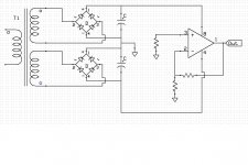
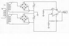
Yes.
Now here are two different schematics. Given the same values for the parts in both circuits which will have less power supply noise on the output?
Attachments
- Status
- Not open for further replies.
- Home
- Member Areas
- The Lounge
- John Curl's Blowtorch preamplifier part II