Now, what do I think about circuit construction? I think that WHEN you use the 'best' parts, the best circuit board material, best soldering quality, etc, etc, then this 'estimate' that I make for the reduction in higher order distortion will drop to ridiculously low levels in normal operation, and 'third order' effects will not dominate. That is what I try to convey here, and one of the 'secrets' of successful audio product design.
Now what about my 'estimate' of the Blowtorch's harmonic distortion?
So what is your estimation , actually ?...
Even a number with one or two order of magnitude error would
be infinitly more accurate that what followed this sentence of yours...
That's the -40
OK, then let's do the math without the need for a codex. If I have a bare bones supply (cheap 10,000uF/25V cap, no fancy choke or extra RC) and a whole pile of circuitry (let's say 100mA of draw), raw supply ripple is 120mV. At your chosen 3kHz, harmonics are -40dB wrt 120mV. A 7815 will knock that down another 55dB (and a 317 with cap bypass will be about a hundred times better, but let's stick with a 7815). 797 knocks that down another 95dB. So there's our line stage. The power amp is likely to have 26dB of gain. Overall, then, we deliver a signal -164dB down from 120mV at the speaker terminals (something less than a nanovolt). I haven't taken the math further, but I bet that's pushing the thermal noise of the voice coil.
Do the math, SY.
Show data to support your claim, John. Or man up and admit that you simply don't have any.
I would like clarification on your criticism, wahab. Did you not understand what I put forth as the METHOD of estimating harmonic distortion with level?
I realize that many of you are probably suspicious of such an easy mathematical process, but I was exposed to it for many years with analog tape recording, in which the 3'rd harmonic (totally dominant because of the tape itself) could be reliably predicted, over and over, with different recording levels, once a single distortion with level was measured.
I realize that many of you are probably suspicious of such an easy mathematical process, but I was exposed to it for many years with analog tape recording, in which the 3'rd harmonic (totally dominant because of the tape itself) could be reliably predicted, over and over, with different recording levels, once a single distortion with level was measured.
Because, the power supply is nice and relaxed doing its job: that's a major part of the story. Stress, nasty current spikes in that area equals crappy sound ...One strong conclusion leaps out though: class A operation gets a lot of the work done. We may already know it, but doesn't hurt to be reminded.
Thanks,
Chris
Frank
Leg pulling.
With waveguides the second conductor has no meaning.
EM waves have already been generated (e.g. by an antenna, a klystron tube) just before the entrance of the wave guide.
We tap the wave’s EM energy after (or just at) the end of the guide through an EM sensor (e.g. antenna)
The wave guide just confines the wave to propagation. Waves are confined inside the wave guide due to total (should) reflection from the wave guide walls.
Cross sectional shape of the guide has to match polarisation mode of the already generated wave. Cross sectional dimensions have to match wavelength.
Electric field is (should be) perpendicular to the wall.
Magnetic field is (should be) parallel to the wall.
These last two could and do happen within a coaxial cable as well.
The similarities stop when we think of the way we feed energy to and tap energy from in the case of the cable .
We apply an electrical potential difference between the inner and outer conductor.
We tap another potential difference between the inner and outer conductor at the far end of the cable.
What happens in between –how to explain the energy propagation- is the puzzle of my late life. The chicken and egg problem.
That’s why I refered to it.
Charge diffusion (ha, ha we can't get away with that so easy), eddy currents generation, counter magnetic action, finally leading to skin effect. All dynamically influenced by time. I agree.
The (many) nonlinearities observed all these years are due to materials variables.
Our recent problem as it seems is not the skin effect’s effects but how the proximity effect’s effects indicate an inherent (theoretical derived) frequency distortion.
Does Fred. W. Grover's book says anything about this distortion?
George
Comments -- skin affect and proximity have the same affect... but are caused by different means. The lowering of inductance is what causes the currents at higher freqs to flow in that region of the 'skin'. But what causes that to happen? The wire(s) geometry causes electromagnetic fields to be concentrated more and less across the conductor. In a round conducting wire the field is concentrated -denser- at the center... thus the center has the higher inductance. Where ever the fields get concentrated, the inductance is increased. Proximity can reduce inductance but it is not evenly distributed or symetrical anymore.. as skin affect is in a single conductor or a coaxial arrangement. does this asymetry result in harmonics generated ... I dont know. Maybe. Or would it present itself as group delay? But would be geometry dependant.
Without further adoooo.... In a coax configuration --> the dc resistance and the high freq 'resistance' from skin affect can be such that the ratios of the two 'resistances' become >>1. If one wanted to maintain a ratio of 1:1, then you could use a twin-axial cable design without using the center conductor at all. the two closely spaced shields or 'tubes' with a thin dielectric between them will do the trick. And, if the two tubes or 'shields' were made of a single layer of spiral wrapped individual insulated wires (small gauge) at 90 degrees to each other, the inductance will be very low and the dispersion will be very low. But the C will be high... no problem if the driving stage has ample current drive capability -- such as a power amp and wire cable interconnect.
Thx- RNMarsh
Last edited:
<snip>
.. but I was exposed to it for many years with analog tape recording, in which the 3'rd harmonic (totally dominant because of the tape itself) could be reliably predicted, over and over, with different recording levels, once a single distortion with level was measured.
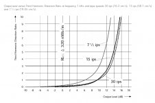
This one? ;-)
Attachments
Are you saying you don't have the gear to make such measurements? Then perhaps you shouldn't be pontificating either.I don't know what would satisfy anyone here. We have many 'retirees' and 'amateurs' doing our 'inventory' when it comes to measurement and distortion estimates.
Samuel Groner has done us all a great service in making such extensive measurements of most common IC op amps and even a few discrete designs.
Do any of you out there do anything useful in this area? Do you have the test equipment to at least go down to 1 part in a million? If not then maybe you are exceeding your qualifications in criticizing us here.
But why not sent Blowtorch to Sam so we can have some proper comparative measurements if you are unable or unwilling to do them yourself? Or are you simply unwilling to publish the results?
All this is useless in the face of poor layout, grounding and decoupling.Now what about my 'estimate' of the Blowtorch's harmonic distortion? .... loadsa pontificating .... If you can show me where I am in error, I would appreciate it.
.... I think that WHEN you use the 'best' parts, the best circuit board material, best soldering quality, etc, etc, then this 'estimate' that I make for the reduction in higher order distortion will drop to ridiculously low levels in normal operation, and 'third order' effects will not dominate.
As you have obviously ignored several clear recommendations on the AD797 datasheet on these issues, it is highly likely your implementation of AD797 is flawed.
But as the thread is about Blowtorch, it is also likely that Blowtorch is wanting on these issues too. Golden Pinnae parts, hand carved by virgins from solid Unobtainium do not preclude the need for basic layout, grounding & decoupling skills.
How about some real 'proof', JC?
This one? ;-)
Very little between 15 and 30 ips ....
All this is useless in the face of poor layout, grounding and decoupling.
As you have obviously ignored several clear recommendations on the AD797 datasheet on these issues, it is highly likely your implementation of AD797 is flawed.
But as the thread is about Blowtorch, it is also likely that Blowtorch is wanting on these issues too. Golden Pinnae parts, hand carved by virgins from solid Unobtainium do not preclude the need for basic layout, grounding & decoupling skills.
A well known objectivist designer who used to post on DIYA up until a few years ago, has this to say about one of John's designs, I quote from his website. Emphasis mine:
HPS 2.0 is still no match for the Vendetta Research and the Pass XONO, when it comes to noise performance. I had the opportunity to reverse engineer both models and I can tell there's nothing very special about these performances, beyond some unobtanium Toshiba JFETs (Vendetta) and some very good practices in wiring and grounding (both models).
Give up guys.... you've tried for months and years to get JC to compare distortion numbers and means and methods... he isnt going to do it. IMO comparing thd and noise and bandwidth becomes a numbers game for marketing. JC has said he belivevs there is more to better audio performance than only those numbers. There are other numbers and there are affects of materials, grounding, pcb artwork/layout and loading and interfacing etc etc etc. Give it a rest.... it aint going to happen the way you want it to. Agree to disagree and move on. There is plenty to discusss besides comparing numbers only. Attention to a LOT of details makes a better product. At this point in the maturity of analog audio design - its all in the details. -Thx RNMarsh
Last edited:
+1 ...There are other numbers and there are affects of materials, grounding, pcb artwork/layout and loading and interfacing etc etc etc. Give it a rest.... it aint going to happen the way you want it to. Agree to disagree and move on. There is plenty to discusss besides comparing numbers only. Attention to a LOT of details makes a better product. At this point in the maturity of analog audio design - its all in the details. -Thx RNMarsh
Frank
Give up guys.... you've tried for months and years to get JC to compare distortion numbers and means and methods... he isnt going to do it. IMO comparing thd and noise and bandwidth becomes a numbers game for marketing. JC has said he belivevs there is more to better audio performance than only those numbers. There are other numbers and there are affects of materials, grounding, pcb artwork/layout and loading and interfacing etc etc etc. Give it a rest.... it aint going to happen the way you want it to. Agree to disagree and move on. There is plenty to discusss besides comparing numbers only. Attention to a LOT of details makes a better product. At this point in the maturity of analog audio design - its all in the details. -Thx RNMarsh
This is correct, we simply have to admit, that standard measurements have only minor importance for high-end design. We would all wish to have well technical grounded receipes for cooking high-end, but a nature of audio is not fully explored yet.
Every succussful high-end designer has its own semi-empirical receipes, and he is not able to explain all possible critical questions regarding them.
For example, russian high-end guru Makarov has the following personal high-end receipes:
1) tubes
2) No GNFB
3) direct coupling (except output trafo)
4) high slew rates of stages, every preceeding stage has factor of two higher slew rate
5) extremely low PS ripples and low noise
6) top quality contacts, silver rotary switch, no relays
7) low input impedance of the amp, around 1 kOhms (this limits possible choice of signal sources)
Using these receipes, he is very successful at marketplace, but is not very regarded among technical experts. Lowering of THD is sipmly a matter of optimisation of individual stages. THD usually does not affect those aspects of sound quality, that are most estimated by high-end buyers.
Last edited:
For everyone to more completely understand:
Analog magnetic tape IDEALLY doubles in distortion for every 3dB rise in level. Of course, it decreases in the same amount for every 3dB fall in level.
This follows the mathematical law of generating 3'rd harmonic distortion.
So: 6dB rise gives 4 times more, 10dB rise gives 10 times more.
With high speed tape, it is VERY consistent with this prediction.
On an early data sheet, I specified .01% distortion, either SMPTE IM or harmonic at 3V out (balanced) for the Blowtorch.
It has been more than a decade since I first made that measurement, but it is consistent to what I normally think important in a maximum acceptable level for a preamp.
It was difficult to get this number, because it is an open loop design.
The Vendetta Research phono preamp could do .01% distortion at 10V out either SMPTE IM or harmonic, because it used feedback in the second gain block.
The price we pay for an open loop design is more distortion at a given output level, and this is why a good deal of matching, and component selection is more necessary than a typical medium or high feedback design.
Therefore the Parasound JC-2 preamp uses global negative feedback to make it easier to build, and it has BETTER specs than the Blowtorch, but it does not necessarily sound as good.
Give up guys.... you've tried for months and years to get JC to compare distortion numbers and means and methods... he isnt going to do it. IMO comparing thd and noise and bandwidth becomes a numbers game for marketing. JC has said he belivevs there is more to better audio performance than only those numbers. There are other numbers and there are affects of materials, grounding, pcb artwork/layout and loading and interfacing etc etc etc. Give it a rest.... it aint going to happen the way you want it to. Agree to disagree and move on. There is plenty to discusss besides comparing numbers only. Attention to a LOT of details makes a better product. At this point in the maturity of analog audio design - its all in the details. -Thx RNMarsh
+2
- Status
- Not open for further replies.
- Home
- Member Areas
- The Lounge
- John Curl's Blowtorch preamplifier part II