LDRs
Hi Mike,
I went down this path myself a few years ago due to the less-than-stellar characteristics of VCAs available in the 1990s, with control noise feedthrough, distortion, etc. The freedom from galvanic coupling between control and audio seemed a no-brainer to me.
I spent quite a bit of time optimizing the design of CdSe optocoupled attenuators at that time, and as I remembered, there were odd distortion issues I could not eliminate due to non-linearities of the CdSe semiconductor itself. Discussions with the (then) Vactec manufacturing engineers revealed that they optimized for speed or dark resistance, not linearity vs. applied voltage. It has been many years, and maybe the current processing of the opto-couplers you reference are better?
Thanks for the update and any data on this issue,
Howard Hoyt
CE - WXYC-FM 89.3
UNC Chapel Hill, NC
WXYC Chapel Hill, North Carolina - 89.3 FM
1st on the internet
Having just said that I'm not thinking about pots anymore I now find myself thinking once again about LDR's and if in light of what I've learnt over the last 2 years and from reading this thread whether I could implement them better than I did last time somewhat close to Pietjers suggestion here http://www.diyaudio.com/forums/anal...uator-new-passive-preamp-102.html#post1392586.
I remember how very impressed I was with the sound when I first built this circuit with the LDRs driven with CCSs - such clarity & verve compared with TVCs. Careful implementation makes a big difference to final perfomance.
I would be interested to hear your impression of LDRs as a breed what you regard as their limitations.
For me one of their biggest strengths is that there are no wipers - every connection can be soldered. (edit: having first cleaned the surfaces)
If I had to use an analogue pot I would make comparisons between LDRs and stepped attenuators but LDRs are much cheaper
Hi Mike,
I went down this path myself a few years ago due to the less-than-stellar characteristics of VCAs available in the 1990s, with control noise feedthrough, distortion, etc. The freedom from galvanic coupling between control and audio seemed a no-brainer to me.
I spent quite a bit of time optimizing the design of CdSe optocoupled attenuators at that time, and as I remembered, there were odd distortion issues I could not eliminate due to non-linearities of the CdSe semiconductor itself. Discussions with the (then) Vactec manufacturing engineers revealed that they optimized for speed or dark resistance, not linearity vs. applied voltage. It has been many years, and maybe the current processing of the opto-couplers you reference are better?
Thanks for the update and any data on this issue,
Howard Hoyt
CE - WXYC-FM 89.3
UNC Chapel Hill, NC
WXYC Chapel Hill, North Carolina - 89.3 FM
1st on the internet
The dark side of the moon, oh yes.the less-than-stellar characteristics of VCAs available in the 1990s
Hy mikelm. can-you give us some more words about the listening feelings differences between the different type of volume control you have experienced ?
About LDRs, how is the attenuation curve ? Close enough to logarithmic ? How is the accuracy between the two channels ?
check out nelson's contribution later in the thread - it's presented very logically.
http://www.diyaudio.com/forums/anal...uator-new-passive-preamp-133.html#post1520215
about my impressions: well, I never did a comparison of all four at the same time - only the old with the new at each changeover and it goes back over about 10 years or so.
At the time each change felt like an upgrade
Also my system is much more refined now than it was during any of the comparisons I made so I would hesitate to comment very much.
But the last time I tried LDRs they sounded less clean than my digital control.
My TVC - Stevens & Billington Mk2 - sounded full bodied but lacking the detail & dynamics of LDRs but I believe the Mk3 had a bit more sparkle.
I thought the digital control would loose the S2N ratio advantage of an analogue pot but I never noticed this subjectively.
Sorry PMA missed that,
No problem at all. I am glad we have some posts with a kind of engineering value in this mad thread.
Thanks for that. I've had a lot of experience with photoconductor-based optocouplers, as Brad Plunkett designed them into the car audio amps for Ford and others that I was obligated to support for a while. Although ultimate audio quality was not the primary criterion, their complex dynamics and history dependence actually did a pretty good job when used in their role as limiters. If it had just been about the sonics we would have been fine, given the application.Hi Mike,
I went down this path myself a few years ago due to the less-than-stellar characteristics of VCAs available in the 1990s, with control noise feedthrough, distortion, etc. The freedom from galvanic coupling between control and audio seemed a no-brainer to me.
I spent quite a bit of time optimizing the design of CdSe optocoupled attenuators at that time, and as I remembered, there were odd distortion issues I could not eliminate due to non-linearities of the CdSe semiconductor itself. Discussions with the (then) Vactec manufacturing engineers revealed that they optimized for speed or dark resistance, not linearity vs. applied voltage. It has been many years, and maybe the current processing of the opto-couplers you reference are better?
Thanks for the update and any data on this issue,
Howard Hoyt
CE - WXYC-FM 89.3
UNC Chapel Hill, NC
WXYC Chapel Hill, North Carolina - 89.3 FM
1st on the internet
But they were the bane for adherence to the quality assurance folks' process capability indices, as they had soooo many attributes based on storage in the dark, temperature, recent history. And as you mention, intrinsic nonlinearity, usually symmetrical about zero, hence producing odd-order harmonic distortion and the usual close-in 2f1 +/- f2 series intermod products. But since in this case they were only invoked, as it were, when other distortions were rampant, the distortion behavior was relatively insignificant.
For level control? Well --- no wiper noise. Difficult to assure accuracy, even with dual parts with interdigitated photoconductors and servos around one of the pair. Without that trick, likely to be all over the map.
Fair enough.At the time each change felt like an upgrade
According to Mr Pass measurements, i wonder if the "speed" feeling of LDRs is not due to the H3 added distortion.
+1I am glad we have some posts with a kind of engineering value in this mad thread.
PMA, many of us here think and agree that you are an outstanding engineer. However, that is not what I am trying to 'show' here or discuss. Engineering can be found in books or in articles. Truly successful audio design takes a little more, and much of the 'more' comes from experience and feedback from others.
For example, what would you think, if you designed and built something with better than average parts, that measured well, YET did not sound good compared to other devices that did the same job? Would you ignore input from others? Would you ignore the lack of interest in the marketplace? IF you ignore outside input, you are destined to fail, at least a certain amount of the time. The only people who will congratulate you are other engineers, interested in your topology and measured results. Please trust me that I have made several products that 'failed' with both 'experienced listeners' and ultimately, the marketplace. Even with MY EXPERIENCE, I have sometimes let a project escape my total control, and someone else, doing the actual manufacture, can change something that makes all the difference. How do we know? Because we have deliberately set out to modify 'failed' amps and preamps, and made them 'right'. Even right enough to be included in my own audio system, or dozens of others.
This is what I hope to put forth, here. What 'works'.
However, on the engineering side:
I have two new books on engineering:
'ANALOG Circuit Design' by Bob Dobkin and Jim Williams
'Build Your Own Transistor Radios' by Ronald Quan
Both are useful, how about you?
Last edited:
It is always interesting that people will go so far, out of the way, to AVOID a single moving contact. Of course, there is always doing something in a new area of electronics, that accounts for some interest. However, if I scold against bad contacts, many here think I am 'over the top'. '-)
I would not bother with a linear light dependent volume control, myself for a number of reasons. However, Constellation, one company I design for, does make a optically controlled switched attenuator that seems to work fairly well. This is digital, mostly, not analog, in operation.
I would not bother with a linear light dependent volume control, myself for a number of reasons. However, Constellation, one company I design for, does make a optically controlled switched attenuator that seems to work fairly well. This is digital, mostly, not analog, in operation.
“there's something there” isn't (dis)proof of a specific physical theory
I respect the effort - but a few numbers associated with the experiment would help – and they need comparison against a model of the effect the test is intended to measure
-154dB (re what?, 2 dB above noise floor?) 2nd is not necessarily a problem with Maxwell's Equations, linear models of "conventional engineering" understanding of "proximity effect"
materials aren't perfectly linear, there may be other effects in play
it is always nice to have controls that show the resolution of the setup, data points showing theory predicted curves, tests at multiple points to see if predicted frequency, amplitude dependencies are being followed
nonlinear magnetic materials are something to look for – nickel plating won't show “is picked up by a magnet” gross magnetism but could be used in end cap construction
another effect is that while field quantities relation to source excitation is linear in free space, and to a high degree in many materials, the forces are proportional to the square of the quantities
as a practical engineer I'd need more numbers but so far I'm not clear why I should worry overmuch about whatever is causing your measured 2nd
you attribute the 3 rd harmonic to TC effect – won't take much more level for it to dominate over the slower growing 2nd
and you don't seem to be crowing about “non-harmonic distortion” just because there is some difference at ~16.2 kHz – why is that?
I really don't see the plot as a reason to rewrite Maxwell's equations
JN
You are a grrfter nerzzog frakidle! Attached is a picture of the test setup and the FFT with the wires close a shown and then pulled back. The third harmonic is identical and extremely low. That would be from resistor distortion not quite being the same. There is a clear spike on the second harmonic with the wires close. It is greater than the thermal distortion.
As this took me 4 hours I am not inclined to do much more.
But the peanut gallery as usual is arrogant and wrong.
ES
I respect the effort - but a few numbers associated with the experiment would help – and they need comparison against a model of the effect the test is intended to measure
-154dB (re what?, 2 dB above noise floor?) 2nd is not necessarily a problem with Maxwell's Equations, linear models of "conventional engineering" understanding of "proximity effect"
materials aren't perfectly linear, there may be other effects in play
it is always nice to have controls that show the resolution of the setup, data points showing theory predicted curves, tests at multiple points to see if predicted frequency, amplitude dependencies are being followed
nonlinear magnetic materials are something to look for – nickel plating won't show “is picked up by a magnet” gross magnetism but could be used in end cap construction
another effect is that while field quantities relation to source excitation is linear in free space, and to a high degree in many materials, the forces are proportional to the square of the quantities
as a practical engineer I'd need more numbers but so far I'm not clear why I should worry overmuch about whatever is causing your measured 2nd
you attribute the 3 rd harmonic to TC effect – won't take much more level for it to dominate over the slower growing 2nd
and you don't seem to be crowing about “non-harmonic distortion” just because there is some difference at ~16.2 kHz – why is that?
I really don't see the plot as a reason to rewrite Maxwell's equations
Last edited:
George it is the 90 degrees of shift at DC that leads me to think what they mean is that if you have less than this amount of shift in your feedback network the circuit will be stable.
Pavel I am glad to see you got that the signal gain is 1 the noise gain is -101 resulting in a noise amplification of -100. You also show that the noise is close to the distortion. For the LM4562 at 2.7 nV/Hz^-2 at 20,000 Hz = 141*2.7e-9 = 382nV And from the lowest distortion graph at 17 volt rails and 3v out into 2K the distortion is shown as a hair less than .00003% or .00003 x .01 x 3 = 900 nV. If you subtract the noise from this Sqrt (900^2-382^2) = 815 nV So the distortion is actually lower than the headline in the spec sheet.
Scott, I don't understand why you are confused. I thought you misreading everything was humor. The graphs in the data sheet are most likely straight from the AP and so are limited by those measurement methods. I don't understand why you keep defending the noise amplifier gain or input impedance. I assume you understand the difference between DC and AC performance.
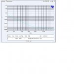
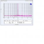
For the non peanut gallery attached are two AP system 2 measurements of a discrete device. It is limited to a gain of 1 so I cannot use the noise gain circuit on it. I show the Distortion versus level graph as the AP does it and then the actual THD structure as the AP measures it at it's limit of sample rate, averages and choice of convertors. (FFT 0db=1V)
I would order in some LM4562's to show the difference between the more limited THD/Level graph vs doing a long FFT analysis which I think would show the headlines on distortion in the LM4562 are still a bit high, but the critcis would just claim parameter variations in production. The point made before and still valid is that the best opamps can be limited by poor use of passives.
Pavel I am glad to see you got that the signal gain is 1 the noise gain is -101 resulting in a noise amplification of -100. You also show that the noise is close to the distortion. For the LM4562 at 2.7 nV/Hz^-2 at 20,000 Hz = 141*2.7e-9 = 382nV And from the lowest distortion graph at 17 volt rails and 3v out into 2K the distortion is shown as a hair less than .00003% or .00003 x .01 x 3 = 900 nV. If you subtract the noise from this Sqrt (900^2-382^2) = 815 nV So the distortion is actually lower than the headline in the spec sheet.
Scott, I don't understand why you are confused. I thought you misreading everything was humor. The graphs in the data sheet are most likely straight from the AP and so are limited by those measurement methods. I don't understand why you keep defending the noise amplifier gain or input impedance. I assume you understand the difference between DC and AC performance.
For the non peanut gallery attached are two AP system 2 measurements of a discrete device. It is limited to a gain of 1 so I cannot use the noise gain circuit on it. I show the Distortion versus level graph as the AP does it and then the actual THD structure as the AP measures it at it's limit of sample rate, averages and choice of convertors. (FFT 0db=1V)
I would order in some LM4562's to show the difference between the more limited THD/Level graph vs doing a long FFT analysis which I think would show the headlines on distortion in the LM4562 are still a bit high, but the critcis would just claim parameter variations in production. The point made before and still valid is that the best opamps can be limited by poor use of passives.
Attachments
Last edited:
I respect the effort - but a few numbers associated with the experiment would help – and they need comparison against a model of the effect the test is intended to measure
-154dB (re what?, 2 dB above noise floor?) 2nd is not necessarily a problem with Maxwell's Equations, linear models of "conventional engineering" understanding of "proximity effect"
materials aren't perfectly linear, there may be other effects in play
it is always nice to have controls that show the resolution of the setup, data points showing theory predicted curves, tests at multiple points to see if predicted frequency, amplitude dependencies are being followed
nonlinear magnetic materials are something to look for – nickel plating won't show “is picked up by a magnet” gross magnetism but could be used in end cap construction
another effect is that while field quantities relation to source excitation is linear in free space, and to a high degree in many materials, the forces are proportional to the square of the quantities
as a practical engineer I'd need more numbers but so far I'm not clear why I should worry overmuch about whatever is causing your measured 2nd
you attribute the 3 rd harmonic to TC effect – won't take much more level for it to dominate over the slower growing 2nd
and you don't seem to be crowing about “non-harmonic distortion” just because there is some difference at ~16.2 kHz – why is that?
That is because I have shown this test many times before. 0 level is the voltage across each resistor in the bridge or 7.9 volts AC RMS.
The noise at 16.2 seems to show up in many of the low level plot the system does. Now if it comes from the computer driving the AP, a switching power supply or whatever I don't know. But I have presented lots of these measurements and it is data I note but don't really worry about.
Did you note the change in fundamental between the measurements? If I were to go further I would add small capacitors with values around the setup change to verify that is what causes it. But as the numbers are of the order I would expect with 2 pF of unbalance it is not worth it to me.
I mentioned I am using Dale CMF55 resistors, you are welcome to check them out. They have also been shown here many times.
You are welcome to repeat the test on your own. We can then compare results. I am not out to prove anything. I was asked to use my test setup for a specific test. I did and I showed the steps to do it and the results.
But for now I will change my PC layout practices and no longer route PC traces directly under components.
Simon, the only thing that can go into -101 is +1 and -101 the signal is in the first 1 then the noise is inverted (theres your *-1) and 100db further down, not 1 multiplied by -100, which would still be -100. its still a gain of -101 you dont count the first unity gain twice just because its inverted
I dont have hardly any of the math for this stuff and that seems pretty plain to me, is it because I dont have the math preconception that I can see it?
I dont have hardly any of the math for this stuff and that seems pretty plain to me, is it because I dont have the math preconception that I can see it?
Last edited:
Indeed: still valid, but order of importance has not been demonstrated. This will be done, and very interesting, when the same measurements will be published between average industrial metal film resistance and top 'quality' parts.The point made before and still valid is that the best opamps can be limited by poor use of passives.
According to the fact that the max acoustic level we can afford is 120db, and the average most silent environment noise is around 30db, I believe (with a margin) anything (noise or distortion) under -100db has no audible effect. Am-i wrong ?
Am-i wrong ?
I doubt it, wont stop us 'just in case' though. if it were ALL about the music we wouldnt be here.
I should say i'm speaking for myself here. the music is still the most important thing, but it sure aint everything.
For me the "awakening" occurred over 25 years ago when my system source was the top of the line Yamaha CD player with a very well engineered digital volume -- still have the unit, and working, makes very nice soundsIt is always interesting that people will go so far, out of the way, to AVOID a single moving contact. Of course, there is always doing something in a new area of electronics, that accounts for some interest. However, if I scold against bad contacts, many here think I am 'over the top'. '-)
-- definitely no moving contacts the full length of the audio path. Once I heard what this was capable of there was no going back ...I've never got this "hangup" about digital volume controls; on the Yamaha I put on a track that was encoded at-60dB, had volume on max; ear pressed against the speaker driver, and was just able to discern digital noise. On normal tracks, with volume down 60dB, no artifacts whatsoever.
Whereas, analogue volume controls drive me batty; for me the signature is a rough edginess that steadily develops in the treble, the quality that makes "bad" recordings sound exactly so ....
Frank
For me the "magic" area is between 60 and 80dB down; try listening to a track encoded at -60dB attenuation without touching the volume control and tell me that I'm wrong ...According to the fact that the max acoustic level we can afford is 120db, and the average most silent environment noise is around 30db, I believe (with a margin) anything (noise or distortion) under -100db has no audible effect. Am-i wrong ?
Frank
I agree. Just BIG margins, for nobody can argue about 'correlated' distortion sounds that some could hear way under noise floor, or 'signature' with invisible inkFor me the "magic" area is between 60 and 80dB down; try listening to a track encoded at -60dB attenuation without touching the volume control and tell me that I'm wrong ...
Some love to cut hairs in four or curl them.
Last edited:
attached are two AP system 2 measurements of a discrete device.
Ed
The 1st attachment (%), is it THD or THD+N ?
The reason I ask is this:
The attached FFT shows
2nd –134db
3rd – 144db
4th –148
5th –146
6th –164
7th –154
8th –154
9th –158
10th –165db
Adding them, it makes for a –137db THD rel. 1V
The % distortion plot shows for the 1V signal level 0.0007% distortion. This correspond to a value of –103db rel. 1V fundamental.
So there is a discrepancy between these two measurements.
FFT shows 34db lower THD than the % plot. (Long averaging can get these superior results, throwing noise out of the picture).
It is limited to a gain of 1 so I cannot use the noise gain circuit on it.
You can do the trick for the x1 gain. Look the resistor values at vacumphile’s attachment (x1 signal gain is the first row of the table)
http://www.diyaudio.com/forums/analog-line-level/146693-john-curls-blowtorch-preamplifier-part-ii-3257.html#post3322940
George it is the 90 degrees of shift at DC
I don’t see the plot extending down to DC, so I am
But it’s not important.
George
Last edited:
- Status
- Not open for further replies.
- Home
- Member Areas
- The Lounge
- John Curl's Blowtorch preamplifier part II