Feedback resistors are CRITICAL. We have known this, for like, forever.
Up until recently I had adopted the money saving stance that Rf + Rg where the most critical positions and bought premium resistors only for those positions.
However, over the course of the last two years in an amplifier design I was working on I changed one by one all of the other resistors in the circuit from cheap industry standard metal films to Caddock TF020 or USF340 & some Caddock MK132s.
My conclusion from this process is that if we are aiming to achieve the best possible sound then every resistor is critical.
I changed the resistors over in what I guessed was order of importance and was surprised when I was getting towards the end of the process that I could clearly hear the effect of each swap.
Ascribing more importance to Rf + Rg also brings the temptation to increase the open loop gain to really cash in on the advantage - I tried this with TF020's & USF340's only in those two positions and the extra OLG brought an overall benefit to the sound. ( I increased the gain by changing the i/p stage load resistor to a CCS ).
However, towards the end of the process, with premium resistors in most positions, when I made this comparison again the amp clearly sounded better in the lower OLG mode.
p.s. I'm not claiming that caddock TF020s etc are the best resistors around - just that they sound much better industry standard resistors
Last edited:
My suspicion is that the quality of manufacturing being significantly higher for the Caddock item is making the difference here; for example the termination of the resistive element to the lead would be substantially better, subtle non-linear behaviour here could have a significant impact on high frequency distortion, which the feedback network always finds more difficult to counteract.My conclusion from this process is that if we are aiming to achieve the best possible sound then every resistor is critical.
I changed the resistors over in what I guessed was order of importance and was surprised when I was getting towards the end of the process that I could clearly hear the effect of each swap.
Frank
does
mean you had 2 "blueprinted" amps (device matching, new R to <1% frequency response difference after swaps) transparent switching and a DBT protocol?
the "zeroth" condition for any of that testing is that you can make 2 amps that do sound alike - can't be distingushed in controlled DBT
in an amplifier design... changed one by one... could clearly hear the effect of each swap...
mean you had 2 "blueprinted" amps (device matching, new R to <1% frequency response difference after swaps) transparent switching and a DBT protocol?
the "zeroth" condition for any of that testing is that you can make 2 amps that do sound alike - can't be distingushed in controlled DBT
Last edited:
My suspicion is that the quality of manufacturing being significantly higher for the Caddock item is making the difference here; for example the termination of the resistive element to the lead would be substantially better
Yes agreed and I suspect that the quality of the actual resistive substrate will also be an element in the mix.
But of these two options I suspect that the termination method may be the biggest culprit in cheap resistors.
Has anyone notice / tested that industry standard surface mount resistors sound / test better that their leaded counterparts ? with me this is only a theory at present.
Last edited:
does
mean you had 2 "blueprinted" amps (device matching, new R to <1% frequency response difference after swaps) transparent switching and a DBT protocol?
the "zeroth" condition for any of that testing is that you can make 2 amps that do sound alike - can't be distingushed in controlled DBT
Hi jcx,
No no no, I was not presenting the results of a formal scientific research like you might expect to find in a journal - just sharing informal findings & ideas in the way that is common in forums like this.
Perhaps we have different ideas about what should or should not be presented here - personally I value any such anecdotal input from anyone who has some experience in a particular area - I don't need any kind of "proof" because I would always check out whatever it was for myself before took it on board anyway.
mike
Thanks for the input, Mikelm. I also use Caddock in the Blowtorch but with the precision power resistors in the power supply. Caddock is in fact another 'superior' manufacturer of resistors that we in hi end know about and use.
Your test procedures are similar to mine, in many ways. Don't let people discourage you. We don't have to answer to any 'stinkin referees'. '-) Just ourselves be true.
Your test procedures are similar to mine, in many ways. Don't let people discourage you. We don't have to answer to any 'stinkin referees'. '-) Just ourselves be true.
lots of guesswork going on here, SMD FTW! when results are presented even subjectively with some background info that can be taken for what it is, but above, you dont have any information, yet you are ascribing possible technical benefits without any substance at all.
what makes you think the terminations on something like a susumu or Vishay SMD is lower quality than caddock? the good industrial/instrumentation grade SMD will have been through much more rigorous testing than the leaded parts, because they have to do serious testing to account for board flex, flex from heating etc and these companies are massive, with massive resources.
what makes you think the terminations on something like a susumu or Vishay SMD is lower quality than caddock? the good industrial/instrumentation grade SMD will have been through much more rigorous testing than the leaded parts, because they have to do serious testing to account for board flex, flex from heating etc and these companies are massive, with massive resources.
Thanks for your honesty. I was reacting that way because your " I could not tolerate ... " seemed excessive to me. If your pot is not noisy when you move-it (dirty, tired or DC in) and not charged in excess (FET ?), i'm not sure the difference is SO obvious.The biggest reason, though, is that I know that my volume control makes a difference, I can hear it
To be totally honest, on my side, the main reasons why we did this resistance array in 1970 was to have some argues during the audio shows, to provide some inputs to the marketing department and to get rid of some returns in the after sales service for noisy pots.
It is like changing all resistors in a preamp: Because you expect a positive change, you will feel a positive change. i'm no sure a blind test would correlate-it.
As far i'm concerned, i have so may things more effective i can change*before* in my system, mainly power supply side !
In recording studios, noisy pots are a real nightmare, the main cause of daily maintenance.
It's not the conventional noisiness of pots that I hear, rather a loss of treble sparkle. If I put on a recording with plenty of fine shimmer from cymbals, or violin solo on a top notch instrument, the loss of quality is obvious as the contact areas of the pot lose their integrity with time; this is why the Lightspeed attenuators and the like have a strong following, once you "tune" into this distortion artifact it sticks out like a sore thumb ...If your pot is not noisy when you move-it (dirty, tired or DC in) and not charged in excess (FET ?), i'm not sure the difference is SO obvious.
To be totally honest, on my side, the main reasons why we did this resistance array in 1970 was to have some argues during the audio shows, to provide some inputs to the marketing department and to get rid of some returns in the after sales service for noisy pots.
It is like changing all resistors in a preamp: Because you expect a positive change, you will feel a positive change. i'm no sure a blind test would correlate-it.
As far i'm concerned, i have so may things more effective i can change*before* in my system, mainly power supply side !
In recording studios, noisy pots are a real nightmare, the main cause of daily maintenance.
")
Frank
Funny, i would describe exactly the contrary. A pot sounds, for me, like a carbon resistor: It *add* sparkles, a little granular sound. With metal film resistor, the sound is more fluid, smooth. Since it can be very subtil, not an obvious difference.It's not the conventional noisiness of pots that I hear, rather a loss of treble sparkle.
For some instruments, mainly in low medium, like male voices or cello, or some bluesy electric guitars i prefer pots or carbon resistances as it adds a little 'body'.
The kind of things we use in various mike preamps, in studio, to add characters to some instruments.
Last edited:
what makes you think the terminations on something like a susumu or Vishay SMD is lower quality than caddock?
I do not think that.
I was comparing specified caddocks with cheap industry standard leaded metal film resistors ( not SMD ones ) and I am personally satisfied that they sound ( much ) better.
I don't have much experience with SMD resistors which is why I was asking a question about them - I'm curious to know if cheap industry standard SM resistors tend to sound better that the leaded equivalents due to different industrial processes - from what you say this may be correct.
Massive companies first legal obligation is to provide maximum dividends to their shareholders - I'm not sure this is necessarily compatible with developing resistors for the hi end audio market. This why it's hard these days to buy good quality semiconductors - the mass market, where maximum profits are, is moving in a different direction.
I would like to add that, with some all digital records, the overall sound is sometime TOO pure, a little empty, or synthetic.
I remember this feeling the first time i listened to the first all digital album "Bop till you drop" from Ry Cooder.
This kind of little 'carbon' distortion, like the one's of the magnetic tapes, helps to bring some life back in a more natural way. It help too to gives an impression of volume or loudness.
I'm not so sure that all distortions are always evil for a home system. We may-be not prefer the same sources if we listen on a Quad or a horn system, too.
I'm not sure, too , that there is not a lot of "cultural" effects in our feelings: i do not feel anything strange any more, years after, with the same Ry Cooder's album. I'm just used to the 'digital sound' ? Or my CD player is better ?
Last edited:
We're getting into the subtle areas of what people are listening to, or for now!I would like to add that, with some all digital records, the overall sound is sometime TOO pure, a little empty, or synthetic.
I remember this feeling the first time i listened to the first all digital album "Bop till you drop" from Ry Cooder.
Having mentioned Rye Cooder, my benchmark here is the Get Rhythm album. This is from a period when many people complained about the mastering style getting a little too clever, in the sense that everything could be highlighted to the max. And this album can be hard work on an out of balance system ...
So what I listen for in this sort of album is the quality of the voices. If there is a synthetic quality to that, then there is something definitely wrong with the playback, a person's singing voice should always have the quality of "realness" to it; unless the voices have been deliberately manipulated, which then should be an obvious "effect". In other words, natural sounds in the mix should sound exactly so, and artificial, synthesised or manipulated elements will clearly show themselves as such, there will be a nice contrast between the two "qualities".
Frank
Last edited:
I remember to have recorded the voices of a well known dancer from "west side story". Somebody had the bad idea to produce him as a singer. This poor guy had a soo poor voice, that we were obliged to add a lot of perifericals to enhance-it and get some presence. Including those stupid 'Aphex". He was singing so much out of tune that we where obliged, believe-me or not, to record *14 tracks* of the same voice, and edit-it word by word !If there is a synthetic quality to that, then there is something definitely wrong with the playback, a person's singing voice should always have the quality of "realness" to it;
If you listen to Rihanna in live concert, you will be panic by the way she is so much out of tune: Sometimes, sound engineers are magicians. Don't blame them or your system if, sometimes, there is i little vocoder sound
and I don't particularly like Ouzo or any pastis from any other culture.
This is good for you Scott. Ed’s invitation calls for liver troubles.
But if you have the chance, try smoked (fume) Grappa from Italy.
Yes, I know the "dilemma" - every recording has already gone through a series of pots back in the studio; therefore why should one extra on the preamp make such a difference?
Part of the answer is that the pot's in the studio generally have to be reasonably decent, robust units; they wouldn't last long in the industry if they were too obviously flaky; another is that these attenuators are constantly being adjusted during the recording session, the contact points are refreshed frequently during this time
Behind the slider, with older console modules, attenuators were not simple potentiometers.
George
Attachments
They where the worse: you can hear little clics or step changes if you moved the sliders, during mix-down, witch is a requisite.Behind the slider, with older console modules, attenuators were not simple potentiometers.
A lot of more recent analog mixing desks used Penny & Gilles sliders, motorized or not, just to control a DC: the sound level was processed then by awful VCAs, full of distortion.
We regret evil potentiometers, at this time
Last edited:
The crowding depends only on frequency, not magnitude. Skin effect, and hence proximity effect, gives a geometric current pattern governed by frequency alone. Look at the maths in any decent EM textbook. That is why, as jcx(?) said, it can be modelled by adding some inductances to parallel paths.
Looking in the time domain, as you seem to be doing, will create complications when the phenomenon is best considered in the frequency domain. Of course the two must give the same results when done properly, but one will often be easier to deal with.
It is that "easier to deal with" that throws everybody off, the path you are using.
Proximity crowding must be considered in the time domain to determine the 2F distortion I speak of. Approximations as you speak of ignore the actual effect, but is certainly useful for integrated effects such as average power dissipation.
Await actual tests before throwing the baby out with the bath water..
btw, this is a very important issue with ramping superconducting magnetsn and high field quality correction magnets..how else would I already understand it?? Wha, independent thinking? Me??
jn
What we have found from experience with audio, both pro and consumer, is that some pots have MEASURABLE distortion, especially when loaded down at the wiper. Other potentiometers have no easily measured distortion but an identifiable 'signature'. It is VERY difficult to get a 'perfect' pot at any price.
Fixed resistors are easier to find that are pretty good and reasonably low priced, but they also suffer from distortion and 'signature'. It is best to get the 'audiophile and engineer approved' resistors. Audiophile for the sound, engineer for the measured distortion as they cost little more than typical resistors and just will work better, and are safer to use, IF you want the best fidelity possible.
Fixed resistors are easier to find that are pretty good and reasonably low priced, but they also suffer from distortion and 'signature'. It is best to get the 'audiophile and engineer approved' resistors. Audiophile for the sound, engineer for the measured distortion as they cost little more than typical resistors and just will work better, and are safer to use, IF you want the best fidelity possible.
JN
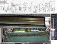
I have had a chance to think about the last set of measurements and the difficulties I had getting nice clean plots. So here are my ideas of the proper way to do this test.
I have on hand 100 of the Dale CMF55s at 10K and 1000 of the Yaego 10K both rated at 1/4W. I will get out my GR Digibridge and match 4 of each. I will punch an aluminum box to hold plastic shell XLRs at at each end. The diamond of resistors will be held in place at the output end by the connecting leads which will be a twisted pair or 18 gauge or so magnet wire. The input side will be 26 gauge or so magnet wire also twisted. I will do measurements at 100, 316, 1000, 3160, 10,000 Hz. One set will be with the input wires perpendicular to the resistor diamond for minimum coupling. The second set will have the input wires dressed close to the top pair and the third test will be with the wires dressed to diagonal resistors.
Scott,
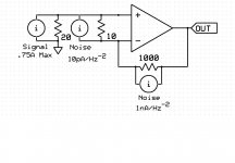
Don't pull the rope! It is not a snake or a tree or even a wall. Don't pull the rope. As usual I think we both have quite different perspectives on the National IC test results. When I presented what I thought was a simple circuit to write the equation virtually no one could do it. So below is attached the schematic of how I perceive their test setup. You are welcome to try the circuit equations or to model it. I suspect my back of envelope calculations are certainly within an order of magnitude or much closer than the factor of 100 you feel is right. (I can do the equations for a "Noise Amplifier" circuit as shown. The basic issues are not what is the noise gain (I think we agree it is 100) but what is the signal gain and input impedance. I have set the input source to model the AP System 2. I think this will help clear the air about the differences we get, (I think we are starting with different assumptions.)
I have had a chance to think about the last set of measurements and the difficulties I had getting nice clean plots. So here are my ideas of the proper way to do this test.
I have on hand 100 of the Dale CMF55s at 10K and 1000 of the Yaego 10K both rated at 1/4W. I will get out my GR Digibridge and match 4 of each. I will punch an aluminum box to hold plastic shell XLRs at at each end. The diamond of resistors will be held in place at the output end by the connecting leads which will be a twisted pair or 18 gauge or so magnet wire. The input side will be 26 gauge or so magnet wire also twisted. I will do measurements at 100, 316, 1000, 3160, 10,000 Hz. One set will be with the input wires perpendicular to the resistor diamond for minimum coupling. The second set will have the input wires dressed close to the top pair and the third test will be with the wires dressed to diagonal resistors.
Scott,
Don't pull the rope! It is not a snake or a tree or even a wall. Don't pull the rope. As usual I think we both have quite different perspectives on the National IC test results. When I presented what I thought was a simple circuit to write the equation virtually no one could do it. So below is attached the schematic of how I perceive their test setup. You are welcome to try the circuit equations or to model it. I suspect my back of envelope calculations are certainly within an order of magnitude or much closer than the factor of 100 you feel is right. (I can do the equations for a "Noise Amplifier" circuit as shown. The basic issues are not what is the noise gain (I think we agree it is 100) but what is the signal gain and input impedance. I have set the input source to model the AP System 2. I think this will help clear the air about the differences we get, (I think we are starting with different assumptions.)
Attachments
- Status
- Not open for further replies.
- Home
- Member Areas
- The Lounge
- John Curl's Blowtorch preamplifier part II