OK, now we are making progress again. You are saying that the delay is frequency-dependent (agreed), may be signal level dependent (agreed in principle but I would like to see the numbers as I doubt it is significant) and may depend on acoustic coupling from the other channel (agreed in principle but even less likely to be significant?).
I like to stay serious about cables.I like serious cables.
"I tend to prefer the ones witch conduct electricity" Peter Walker.
That is exactly the way i proceed.A quick way to "test" this is to switch your attention entirely to something else
The best mastering guy, in Paris, was always leaving the room, after a tune was equalized and compressed for the grooving process, letting-you alone to listen at it before the burning.
I asked why he did that: "Just to listen to it from the next door, reading some paper, to make sure the balance is OK from there."
OK, now we are making progress again. You are saying that the delay is frequency-dependent (agreed), may be signal level dependent (agreed in principle but I would like to see the numbers as I doubt it is significant) and may depend on acoustic coupling from the other channel (agreed in principle but even less likely to be significant?).
No acoustic coupling.
What I am saying is that any delay of part of the frequency content of a stereophonic signal can shift the perceived image. It requires a central image in the field upon which a human can reference to because head positioning uncertainties will swamp un-referenced positions.
For a monophonic presentation, time delay of part of the spectra can result in a depth change of that part, but never a side shift.
Discussion of audibility requires understanding audibility. Welcome to my world. Please, pull up a seat and stay a while..
")
edit: my world being one in which I had a long and steep learning curve as well..
cheers, jn
btw, that is one big problem I have found with 11 band eq's...If you dont get both channels exactly symmetrical, it is easy to find that the sibalance of a female vocal is shifted to one side of the fundamental..a disembodiment so to speak..
ps. Please read my content w/rt to hearing several times prior to responding. I've been quite clear in the bulk of my posts, and am spending a lot of effort duplicating verbage.
Last edited:
We are talking of differential delay, not delay.
We are talking first about two types of differential delays.
1. Delay within the same channel, but dependent on frequency due to the line to load mismatch and wildly varying load impedance vs frequency.
2. Delay in both channels of a part of the spectra uncorrelated to a common signal which is presenting as at center of soundfield. For example, a centrally positioned bassist and a voilin shifted to the right by way of temporal and intensity differentials.
I agree that we are less sensitive to it at low frequencies. Why do you believe the delay is more for low frequency audio? Not all speaker impedance curves peak at bass.The delay will be greater for lower frequency signals, but there it will presumably do less harm.
Work. (not just large ones however)I thought your world is large superconducting magnets?
But that is not my entire world. Besides, I was referring to a world requiring a learning curve..
jn
Fux, now we know what is going on in cables! '-) (and equations)
Sigh..I saw that typo too late...
I was surprised it made it past the word robo-police.
jn
DF96, I am still with you on this delay thing, UNTIL it is shown to me that TINY time delay differences can be detected by humans either with frequency or differentially. Also, it should be clearly stated, by example, how much a time delay can be generated by a typical passive cable with frequency. Without real numbers, this is just speculation, not fact.
Moulton does introduce inter-channel delay - to aid "panning" but lowest delay mentioned is 100us:
Moulton Laboratories :: Principles of Multitrack Mixing: The Phantom Image
a older summary paper on lateraliztion - suggests differential time sensitivity goes away above ~ 1.5 kHz
http://web.mit.edu/hst.723/www/ThemePapers/Binaural/Grantham95.pdf
I would like to see the electrical cable/loudspeaker Z interaction numbers showing this 10us group delay modulation in the electrical domain - below 1.5kHz
you certainly can get (and measure) Doppler modulation with large cone excursion
Last edited:
Coax IC's run 1/sqr(epsilon r) at high frequencies, generally 60% C give or take, so we agree.
Speaker cables will vary quite a bit depending on the cable geometry. Of all the ones I've seen, 4 ns per foot has been the max.
Prop velocity is inherent in the cable geometry, not the termination at the end.
Agreed. Another way to look at it is by calculation of the energy stored within the cable. At pseudo-DC, which is generally the entire audio band plus, if the cable energy storage is predominantly capacitive, the amp will see that.
Agreed. The only caveat to that is trying to measure in the audio band and how the meter interprets the results. Any line based delay mechanism will not be distinguishable from reactance/resistance. Basically, most meters simply calculate the V/I phase shift at the two terminals and calcs the amount of 0 degree shift signal vs 90 degree shift.
That is why I prefer to actually measure at the load. But that's a PITA..
pps..here is the calc of energy storage within a cable with load varied. I could've provided a normalized graph, but it is scaleable and consistent, it's most important feature is showing what the amp sees as line/load mismatch.
It basically shows that when there is a mismatch, the line has to charge either magnetically or electrically in order for the load to see the V/I demands expected. And when matched, the travelling wave from the source to the load completely charges the line and provides the load what it needs in terms of V/I. Don't be thrown off by the units btw, as a simple calculation of a 10Khz square wave energy per lobe will show that the energy levels displayed cannot be brushed aside.
jn
Agreed, but at a typical cable characteristic impedance of 100 ohms, cable energy storage on the graph is only about 1 microjoule. That would seem to be pretty small, and it is only about 3 times greater than that at a perfect match.
Cheers,
Bob
Please re-read the last paragraph..Agreed, but at a typical cable characteristic impedance of 100 ohms, cable energy storage on the graph is only about 1 microjoule. That would seem to be pretty small, and it is only about 3 times greater than that at a perfect match.
Cheers,
Bob
specifically..Don't be thrown off by the units btw, as a simple calculation of a 10Khz square wave energy per lobe will show that the energy levels displayed cannot be brushed aside.
jn
I'm working (slowly) to change my system for an active one. Using my digital filter (modified DCX2496).
In this filter, the output stages active devices will be able to power any charge, including low impedance headphones. Symetrical.
The output will carry the signal always at max level.(1.25Vrms) to optimize the s/n ratio.
Each output side will be protected by a 47 ohms Ohm serial resistance, both to prevent any EMI/RFI to feed the feedback, and to tune source's impedance for the 100 Ohm network cable.
The connection to my enclosures will be done with a cat6 cable. Pair 1 for basses channel, pair 2 for horn channel, pair 3 for power on command of the enclosure's amps, pair 4 for the remote digital command of the level.
Enclosure's side, a 100 ohm load at the symmetrical input of my 2 audio interfaces in order i can keep alive a minimal respect from Jneutron.
This circuit will receive the level command and tune the audio level with a switched array of resistance for each amp simultaneously (MOSFETs for commutation).
Bass amp will be a class D one, horn amp will be my Class Ab mosfet current feedback one.
Did i have to worry about my 50cm loudspeaker's cables between amps and speakers ? (;-)
Well, i will use big wires for my bass speaker, and 4x cat 6 for my 6 ohm horns (because i have them) . All speakers zobel for flat 6 Ohm impedance including resonnance.
How do-you feel this project ?
Which connectors for the network cable ? Shielded RJ45 safe enough ?
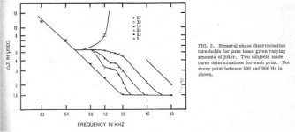
a older summary paper on lateraliztion - suggests differential time sensitivity goes away above ~ 1.5 kHz
See attached. Note that the same paper has a graph which takes it out to 12Khz.
For unjittered sine waves, the summary you speak of is consistent with this data. It is about 5 uSec in the 500 to 1000 hz range.
What cone excursion is required for jittering at up to 2,4, and 6 uSec, assuming 25 C air?
I was referring to time of flight, not velocity of emitter.you certainly can get (and measure) Doppler modulation with large cone excursion
jn
Attachments
Last edited:
That is NOT what i have experienced, neither in measurements, neither in listening. Or at a so little level of influence that i neglect it.Cables always make difference, even with low Zout power buffers. These posts show that many have no experience with top home audio.
Any number as a proof of your assertions, or just your personal feelings ?
(No comment about 'no experience', and my system is >500V/µs and 3Mhz flat able)
Last edited:
Look more carefully, John: those electrolitics caps are only in a parallel resonant compensation network RLC at a *very low* frequency (30Hz) and very little frequency range: So, minimal influence, verified with careful listening.Esperado, you also don't think that caps make a difference either. This is shown by your loudspeaker crossover cap selection.
I work on a completely different level, Esperado. We would not put electrolytic caps in our loudspeaker crossovers.
Distortion of an electronitic cap at 30Hz ?
Any other solution to bring the needed 5000µf ?
And about the completely different level, i doubt any manufacturer would use so big caps and air coils than us: Too heavy, too expensive.
I am not working with magic, but i try to be clever as much as possible.
Last edited:
- Status
- Not open for further replies.
- Home
- Member Areas
- The Lounge
- John Curl's Blowtorch preamplifier part II