Non-trivial, true. Straightforward, though. Given a line, and a load, then currents and voltages can be calculated anywhere. RF designers do this all the time. They consider lines with lengths which are significant when compared with a wavelength. Audio is simpler in that sense. I can't quite put my finger on what it is you seem to have failed to grasp. I assume you have read the standard textbooks on the full transmission line theory? Most just give the simpler RF plus small attenuation model.jneutron said:Trivial when the load at the other end is exactly compatible with the line. Not so when we require the line support a current/voltage characteristic which is not what the line is designed to support.
No, I have assumed that interchannel delays due to this phenomenon will be negligibly small. Your calculation gives total delay, not interchannel delay - which will be much smaller.You have adopted the assumption that interchannel delays are unimportant.
Help! I found an old notebook with some of my stuff that has been stored for at least 25 years. It goes back to 1959 for the first entry, so it is interesting (to me).
However, this page has an entry that must be between 45 and 50 years old, but I can't exactly place its origin. Can any of you math wiz's help?
The last is the relationship between the divergence of the E field as a result of the volume density of charge. Spinoff of the electric fux theorum (electrostatics).
I can only recall when they are written on bar napkins, the notebook throws me off.....
Yah, the threw me off...so did the penmanship..
jn
Haven't you guys ever seen a spiral notebook before? What throws me off is the WATER DAMAGE. I have to keep this notebook in my lab, away from the living quarters, as it smells so moldy, but it is an INSIGHT for me to find it, when most of my past history was lost in the firestorm over 21 years ago.
Non-trivial, true. Straightforward, though.
Semantics. But we agree.
Given a line, and a load, then currents and voltages can be calculated anywhere.
Nobody has stated otherwise.
I can't quite put my finger on what it is you seem to have failed to grasp.
That much is clear.
Your model of human hearing needs to be reconsidered, as it is quite flawed.No, I have assumed that interchannel delays due to this phenomenon will be negligibly small. Your calculation gives total delay, not interchannel delay - which will be much smaller.
An image within a soundfield which is not centered within the soundfield will shift position with respect to a central image when both channels are delayed the exact same amount.
This is where you are lost. Your understanding of human hearing capability is only valid for monophonic reproduction.
I went through this learning curve about 12 years ago. You are at the start of a journey, I hope you take it.
Your E/M and physics is very good. That is not what you are missing.
jn
ps. My statements are not meant to be condescending..my apologies if they appear as such.
You are of course, incorrect.
There are 4 very important things you must remember.
1. There are no lumped element models presented which consider the speed of propagation along the cable. At the microsecond level where humans ability to discern interchannel temporal differences, this can not be ignored.
2. A load at the far end of a cable which has a V/I characteristic which is not identical to that cable, will require a different current than that which the cable will propagate at it's characteristic velocity. The RLCG model assumes instantaneous communication.
3. Measurement of these delays within the audio band is extremely difficult given the overall lack of ability of most to understand and implement a wideband test setup with the necessary capabilities, as well as a lack of adequate hardware.
4. Discussion with you regarding our different thinking on this topic has been nothing but pleasure for me. I do not care if you are wrong, or if I am wrong. This discussion is the way it should be. I thank you for this.
jn

It is useful to bear in mind that signal propogation in cables with typical dielectrics is on the order of 1.5 ns per foot. This varies only a little bit as a function of mis-termination. We should also not confuse phase lag created by LCR lumped-element effects with propogation delay.
Many loudspeakers become inductive at frequencies above the audio band, and it is often beneficial to include a Zobel network at the loudspeaker terminals (or inside the loudspeaker) to maintain its nominal resistive characteristic to high frequencies. This tends to mitigate speaker cable transmission line effects at high frequencies. There is a discussion about this in my book "Designing Audio Power Amplifiers". Often that "nominal" resistance can be set to the characteristic impedance of the cable, so that at high frequencies the cable sees an approximately-matched far-end termination.
It can be especially interesting to measure the impedance vs frequency as seen looking into a 10-foot length of speaker cable when it is terminated in (a) a short; (b) an open; (c) 100 ohms (often near the characteristic impedance of many speaker cables); and (d) 8 ohms. This measurement should be done out to at least 10 MHz.
Cheers,
Bob
Many of the variables reported by listeners which drive engineers nuts are unknown from one place to another. For example, lets say you do not have a wood floor raised from the earth. But instead, live in a high-rise apartment/condo. A steel and concrete floor/walls... a ground plane. Does that grounded flooring (concrete and rebar/I-beams) change the cables L or C, coupling or interference when placed against the floor (ground)? Test it rather than assume. What affect would there be when you raised them off the ground/floor? [I'm not telling] -RNM
Hi Richard,
My speaker cables are raised from the floor by ceramic insulators.
All this implies, regarding time delays and impedance matching, to me, is that connecting cables can therefore be VERY IMPORTANT as they might upset time delays with frequency that might possibly be detected by the human ear. A wonderful approach to answering why cables do not usually sound the same.
I like serious wire too!
Hi John,
It looks like NeoTech cables. I use them for interconnect and speaker cables.
Coax IC's run 1/sqr(epsilon r) at high frequencies, generally 60% C give or take, so we agree.It is useful to bear in mind that signal propogation in cables with typical dielectrics is on the order of 1.5 ns per foot.
Speaker cables will vary quite a bit depending on the cable geometry. Of all the ones I've seen, 4 ns per foot has been the max.
Prop velocity is inherent in the cable geometry, not the termination at the end.This varies only a little bit as a function of mis-termination.
Many loudspeakers become inductive at frequencies above the audio band, and it is often beneficial to include a Zobel network at the loudspeaker terminals (or inside the loudspeaker) to maintain its nominal resistive characteristic to high frequencies. This tends to mitigate speaker cable transmission line effects at high frequencies.
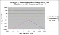
Agreed. Another way to look at it is by calculation of the energy stored within the cable. At pseudo-DC, which is generally the entire audio band plus, if the cable energy storage is predominantly capacitive, the amp will see that.
It can be especially interesting to measure the impedance vs frequency as seen looking into a 10-foot length of speaker cable when it is terminated in (a) a short; (b) an open; (c) 100 ohms (often near the characteristic impedance of many speaker cables); and (d) 8 ohms. This measurement should be done out to at least 10 MHz.
Agreed. The only caveat to that is trying to measure in the audio band and how the meter interprets the results. Any line based delay mechanism will not be distinguishable from reactance/resistance. Basically, most meters simply calculate the V/I phase shift at the two terminals and calcs the amount of 0 degree shift signal vs 90 degree shift.
That is why I prefer to actually measure at the load. But that's a PITA..
pps..here is the calc of energy storage within a cable with load varied. I could've provided a normalized graph, but it is scaleable and consistent, it's most important feature is showing what the amp sees as line/load mismatch.
It basically shows that when there is a mismatch, the line has to charge either magnetically or electrically in order for the load to see the V/I demands expected. And when matched, the travelling wave from the source to the load completely charges the line and provides the load what it needs in terms of V/I. Don't be thrown off by the units btw, as a simple calculation of a 10Khz square wave energy per lobe will show that the energy levels displayed cannot be brushed aside.
jn
Attachments
Last edited:
All this implies, regarding time delays and impedance matching, to me, is that connecting cables can therefore be VERY IMPORTANT as they might upset time delays with frequency that might possibly be detected by the human ear. A wonderful approach to answering why cables do not usually sound the same.
John.
Congrats.
It's about time.
You have made my day, I look forward to the future..
jn
ps...a wonderful approach to possibly answering why cables may not sound the same. It needs vetting by others in a repeatable and testable fashion. Until that occurs, it cannot be assumed as correct.
Last edited:
If both channels are delayed by exactly the same amount then there cannot be any image shift. It is as though the same performance was started a little later in time but in exactly the same place. Either I have completely misundestood you, or you have not said what you intended to say.jneutron said:An image within a soundfield which is not centered within the soundfield will shift position with respect to a central image when both channels are delayed the exact same amount.
This is where you are lost. Your understanding of human hearing capability is only valid for monophonic reproduction.
If both channels are delayed by exactly the same amount then there cannot be any image shift. It is as though the same performance was started a little later in time but in exactly the same place. Either I have completely misundestood you, or you have not said what you intended to say.
You have completely misunderstood me.
As I said, the central image will remain locked in place.
Side images will not remain in place when there is a central image available for the mind to reference.
As I said, this is because you are only considering monophonic reproduction.
Ah, forgot...remember, the delay caused by the line is dependent on the line to load mismatch. That is heavily dependent on frequency because the load impedance is heavily dependent on frequency. It allows some of the spectra to be delayed more than others, it allows signal content to modify the impedance of the load (recall the e = Ldi/dt + I dL/dt discussion) such that some spectra on each channel can be delayed based on other content of the channel. edit( and that completely ignores driver position, they can move +/- Xmax). Low frequency dithering of the ITD also impacts localization sensitivity. Published by some guys a while ago, '72 or '74 I think..
Side images in a stereo reproduction is discerned by both ITD and IID. When the ITD is affected on side images, they will shift relative to an image with zero ITD.
jn
ps..the bottom line? I personally would recommend choosing line impedance to get close to the driver impedances in the audio band. 20 ohms or so. Assume 1 wire pair as 100-150, I'd go 5 or 6 pairs..but I'd use 16 or 18 awg. Twisted pairs, braided, who cares.
Last edited:
If both channels are delayed by exactly the same amount then there cannot be any image shift.
Why? Both channels carry different signal information.
A constant delay in both channels of 10 us can simply be removed by pressing the play button 10us earlier. Image position is caused by the difference in signal timing, not the absolute value. I am certainly not considering monophonic reproduction.
Please try to explain your position again, as I am baffled by what you appear to be saying.
Please try to explain your position again, as I am baffled by what you appear to be saying.
- Status
- Not open for further replies.
- Home
- Member Areas
- The Lounge
- John Curl's Blowtorch preamplifier part II