Attachments
I have. It seemed fine.
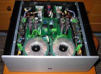
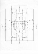
The schematic isn't that mysterious and can be pieced together from knowing the topologies that John generally uses,
What is intellectually interesting to me is why THAT topology and not the many others available then and since? That's where the learning for me is of interest. Not blindly copying it and/or a sim of it for DIY build. Its in that distillation of many issues into a compact circuit that best meets the goals. Knowing the right goals has to be known to get the design distilled.
Also the pcb has advanced ground routing/guide paths and the like which is not blindly done, either. That is nearly a lot art. -RNM
Last edited:
Does mosfets models follow exactly gate capacitors behaviors ? (real question)Does your simulation show it?
Does mosfets models follow exactly gate capacitors behaviors ? (real question)
THEY like to be superior and disdainful. Same manner is sometimes needed to reply.
The question remains if it is the right track to follow, in order to participate at any progress ? I mean, pairing and choosing parts to minimize their defects (sometimes in a very empirical and time consuming way) at a given historical moment...Its in that distillation of many issues into a compact circuit that best meets the goals.
Or find way, working on topologies, to compensate them with more industrial/ low priced parts for same kind of result (listening pleasure and credible make believe).
When i first saw the price of the Blowtorch, i immediately calculated the number of records i can buy with it.
Can-we imagine, in a near future, that simulators can use random statistical values for components, use the board's layouts to simulate parasitic inductances and capacitances ?Never seen a model that would reliably reveal parasitic HF/UHF oscillations.
I was VERY surprized when Scott said they where only use simulators at AD.
And because i'm very new to simulators, i have a big problem to evaluate how much i can rely on them.
Around this time, I recall Apple Computer making a BIG MISTAKE in their product. They made the Apple II computer with a number of gold plated plug-in slots, so that accessories, including extra memory could be added.
Unfortunately they FORGOT to gold plate the plug in board connections, so you had a gold-tin interface. In a relatively short period of time, the connections failed, but the board function could be recovered by just cleaning them and putting them back. Cramolin was first brought out to address problems like this. Later, it was pressed into audio service.
I think it's been around since before WWII first known as Gramolin.
THEY like to be superior and disdainful. Same manner is sometimes needed to reply.
So that we are clear, I know and you know what the behavior will
be, but the neophytes who lurk here deserve to be clued in. And I was
perfectly serious - I am interested whether the simulations will show the
parasitic oscillation.

Positive feedback by current had been used way before. Even Heathkit had tube amp with such thingy implemented, for sale. How it could be patented after that?
Wavebourn, here is the patent. Read it and commend. It is not only about PFB by current.
Loudspeaker lower bass response using negative resistance and impedance loading - Stahl, Karl Erik
George
Wavebourn, here is the patent. Read it and commend. It is not only about PFB by current.
Loudspeaker lower bass response using negative resistance and impedance loading - Stahl, Karl Erik
PFB by current causes negative impedance, plus filter on input causes some boost below Fs. What is different in this article, a language: they mixed electrical correction with mechanical formulas.
I did something similar long time ago because in socialist economy I could not find drivers except cheap ones made for consumer market and some few exemplars made for movie theaters that did not go below 60 Hz. I used simple discrete stages that provided 12 db/Oct boost below Fs. And gave up because it increases distortions of the speaker and decreases max SPL because gain in reproduction of lower frequencies is the result of either higher excursion, or lower power on higher frequencies than on frequencies below Fs. If you add 12 dB of voltage gain on an octave below how much power do you loose if excursion is still the same, no more than Xmax?
But it worked well in a small table radio, when I combined volume control with HPF: decreasing volume I made wider frequency response using excess power. People were surprised: "So big sound from so small radio!"
Something similar was made in German pre-war radios, but people misunderstood it attributing the theory behind it to Fletcher and Munsen curves.
Last edited:
So that we are clear, I know and you know what the behavior will
be, but the neophytes who lurk here deserve to be clued in. And I was
perfectly serious - I am interested whether the simulations will show the
parasitic oscillation.
Thanks for mentioning the likely behavior --- I hoped someone would
To show VHF/UHF oscillations, I suspect a really accurate model that includes package parasitics would be a good start, and that coupled with a little real-world trace inductance, as well as the lead inductance of the caps. Some of the simulators will simply not pursue a fine-enough mesh to show such behavior, although generally one can go in and change the step time to, say, 100ps, and coax things into revealing their secrets. Doing this with some 8GHz transistors in a Wilson mirror showed that his ubiquitous circuit could be unstable, even with some emitter ballasting.
The first simulator I used would simply refuse to even run if it thought it would take a long time and p*ss off the user. It was predicated on much slower machines than we have today.
Unfortunately, that is not correct. John is on the money here, firstly there is a correctly functioning circuit, and then there is dealing with all the 2nd, 3rd, whatever, effects. An extremely competent system can be built by only worrying about technically correct circuits and components, but it won't work as well as it could, unless by fluke.Incorrect (assuming you are speaking about IC's or PC's)
Any modification of the ground loop path will modify the system. Flux loop trapping is the culprit here, not any material properties of the cables.
I am fortunate enough to be easily able to hear the difference between a competent system, and an optimised one; but, unfortunate enough not to be in the industry and have access to the right test gear, to be able to attempt to measure what's going on ... I've got to where I have purely as a hobbyist. I'm certain there are very reasonable and straighforward causes for these behaviours but I'm not in a position to properly investigate and/or theorise on the cause and effect relationship.
Frank
Err.rrh! Actually he is using dat evil electrical stuff to magically conjure up REAL mechanical stuff. When you switch on ACE, the cone IS heavier, with lower resonance, less compliance, more Rem bla bla. You can physically measure the changes in the mechanical bits.PFB by current causes negative impedance, plus filter on input causes some boost below Fs. What is different in this article, a language: they mixed electrical correction with mechanical formulas.
Oh! and distortion is reduced A LOT too.
My lawyers will be in touch for infringement of my Powered Integrated Super Sub patentsI did something similar long time ago .... I used simple discrete stages that provided 12 db/Oct boost below Fs. And gave up because it increases distortions of the speaker and decreases max SPL because gain in reproduction of lower frequencies is the result of either higher excursion, or lower power on higher frequencies than on frequencies below Fs. If you add 12 dB of voltage gain on an octave below how much power do you loose if excursion is still the same, no more than Xmax?
But it worked well in a small table radio, when I combined volume control with HPF: decreasing volume I made wider frequency response using excess power.
Last edited:
B&W have a unit out that does this intelligently, the size of conventional PC speakers. All done in DSP, heavy bass boost up to a certain volume at which point the bass EQ is manipulated so that the drivers are never pushed beyond what's a reasonable excursion. The end result is a coke can sized system which can bowl people over with its "big" sound ...I did something similar long time ago because in socialist economy I could not find drivers except cheap ones made for consumer market and some few exemplars made for movie theaters that did not go below 60 Hz. I used simple discrete stages that provided 12 db/Oct boost below Fs. And gave up because it increases distortions of the speaker and decreases max SPL because gain in reproduction of lower frequencies is the result of either higher excursion, or lower power on higher frequencies than on frequencies below Fs. If you add 12 dB of voltage gain on an octave below how much power do you loose if excursion is still the same, no more than Xmax?
But it worked well in a small table radio, when I combined volume control with HPF: decreasing volume I made wider frequency response using excess power. People were surprised: "So big sound from so small radio!"
Frank
Err.rrh! Actually he is using dat evil electrical stuff to magically conjure up REAL mechanical stuff. When you switch on ACE, the cone IS heavier, with lower resonance, less compliance, more Rem bla bla. You can physically measure the changes in the mechanical bits.
Yes, it is true that it is harder to push the cone. Mechanically. As if it's mechanical properties changed. What actually changes PFB, electro-mechanical properties of the system that includes both speaker and amp.
Oh! and distortion is reduced A LOT too.
C'mon!
- Status
- Not open for further replies.
- Home
- Member Areas
- The Lounge
- John Curl's Blowtorch preamplifier part II